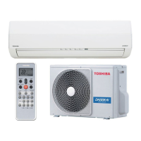
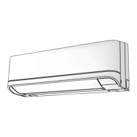
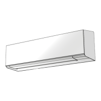
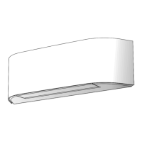
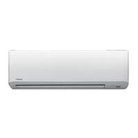
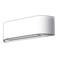
Do you have a question about the Toshiba RAS-B10GKVP-E and is the answer not in the manual?
General safety advice for operation and servicing, including power cord specifications and trial operations.
Safety precautions for handling R410A refrigerant, installation tools, piping, and power disconnection.
Safety guidelines for installation location, electrical work, grounding, and protection against external factors.
Safety guidelines for handling R410A refrigerant during installation and servicing, including pressure and leakage.
Procedures and materials for refrigerant piping installation, including flare/socket joints and brazing techniques.
Detailed wiring diagram for the indoor unit, showing connections to the main P.C. board.
Detailed wiring diagram for the outdoor unit, illustrating connections between P.C. boards and components.
Overview of the air conditioner's control system, roles of indoor/outdoor units, and communication signals.
Safety precautions, optional parts, accessories, tools, and site preparation for installation.
Initial steps for diagnosing issues, including power checks, primary judgments, and inverter diagnostics.
Using remote controller self-diagnosis, LED indicators, and symptom analysis for fault identification.
| Type | Split System |
|---|---|
| Cooling Capacity | 2.5 kW |
| Heating Capacity | 3.2 kW |
| Refrigerant | R32 |
| Indoor Unit Dimensions (W x H x D) | 798 x 293 x 230 mm |
| Outdoor Unit Dimensions (W x H x D) | 660 x 530 x 240 mm |
| Weight (Indoor Unit) | 9 kg |
| Power Supply | 220-240V, 50Hz |
| Noise Level (Outdoor) | 49 dB(A) |


