Do you have a question about the Toshiba RAS-B10J2FVG-E and is the answer not in the manual?
Graphs illustrating compressor speed vs. current for cooling and heating modes.
Charts showing how cooling and heating capacity change with outdoor temperature.
Essential safety precautions for handling R32 refrigerant during installation and servicing operations.
Guidelines and specifications for installing refrigerant piping using copper pipes and joints.
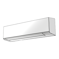
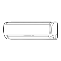
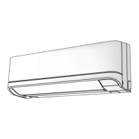
Detailed diagrams and dimensions for the indoor unit assembly.
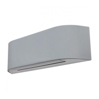
Detailed diagrams and dimensions for the outdoor unit assembly.
List and specifications of electrical components for the indoor unit.
List and specifications of electrical components for the outdoor unit.
Diagram illustrating the refrigerant flow and components within the system.
Table showing operational parameters like pressure and temperatures under different conditions.
Block diagram showing the control functions and signal flow for the indoor unit.
Block diagram illustrating the control functions and signal flow for the outdoor unit.
Overview of the air conditioner's capacity-variable control system and unit communication.
Sections covering various operational modes like cooling, heating, auto, dry, and fan controls.
Explanation of the automatic restart feature after power interruption.
Details on remote control operations, including timers, special modes, and settings.
Description of indicators and buttons on the indoor unit's control panel.
Diagrams showing the placement and mounting of indoor and outdoor units.
List of optional parts, accessories, and special tools required for installation.
Detailed steps and guidelines for installing the indoor unit.
Guidelines and precautions for installing the outdoor unit in various environmental conditions.
Initial checks for power supply, voltage, and basic operation status.
Methods for initial diagnosis including LED flashing and basic checks.
Interpreting flashing patterns of the indoor unit's LED for self-diagnosis.
Using the remote control in service mode to retrieve and interpret check codes.
Troubleshooting guides based on specific symptoms like no power or fan issues.
Diagnosing issues related to interconnecting and serial signal wiring.
Detailed troubleshooting for specific check codes like 1C and 1E.
Procedures for diagnosing and troubleshooting problems with the outdoor unit.
Methods for checking the functionality of main components like PC boards and sensors.
Step-by-step guide for disassembling and replacing parts of the indoor unit.
Procedure for replacing the microcomputer assembly and related components.
Instructions for disassembling and replacing parts in the outdoor unit for specific models.
Instructions for disassembling and replacing parts in the outdoor unit for specific models.
Exploded diagrams and a comprehensive parts list for the indoor unit.
Detailed list and exploded view of electronic parts for the indoor unit.
Exploded diagrams and parts list for the outdoor unit (RAS-10, 13J2AVSG-E models).
Exploded diagrams and parts list for the outdoor unit (RAS-18J2AVSG-E model).
Exploded diagrams and list of electronic parts for the outdoor unit (RAS-10,13J2AVSG-E).
Exploded diagrams and list of electronic parts for the outdoor unit (RAS-18J2AVSG-E).
| Brand | Toshiba |
|---|---|
| Model | RAS-B10J2FVG-E |
| Category | Air Conditioner |
| Language | English |