Do you have a question about the Toshiba RAS-B10J2KVG-E and is the answer not in the manual?
Precautions for safe installation and servicing of R32 refrigerant.
Schematic diagram of the refrigerant cycle for various models.
Diagrams showing installation layout and clearances.
Details on optional installation parts and fixing arrangements.
Instructions for electrical connections and wiring.
Initial checks for power supply, voltage, and normal operation.
Methods for initial diagnosis of troubles.
How to interpret flashing LEDs for self-diagnosis.
Guide to using the remote controller for self-diagnosis.
Troubleshooting symptoms for the indoor unit and remote controller.
Diagnosis of inverter assembly issues for specific models.
Steps to determine if the outdoor fan motor is functioning correctly.
Procedures for replacing main parts of the indoor unit.
Procedures for detaching and attaching parts of specific outdoor units.
Procedures for detaching and attaching parts of specific outdoor units.
| Cooling Capacity | 2.5 kW |
|---|---|
| Heating Capacity | 3.2 kW |
| Energy Efficiency Ratio (EER) | 3.21 |
| Refrigerant | R32 |
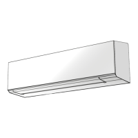
| Indoor Unit Dimensions (HxWxD) | 293x798x230 mm |
| Weight (Indoor Unit) | 9 kg |
| Energy Efficiency Class (Cooling) | A |
| Energy Efficiency Class (Heating) | A |
| Power Supply | 220-240V, 50Hz |
| Coefficient of Performance (COP) | 3.61 |
| Type | Split System |
| Noise Level (Outdoor) | 50 dB(A) |