220–240V ~50Hz
MICRO-COMPUTER BLOCK DIAGRAM
Driver circuit
of P.M.V.
Heat exchanger
temp.sensor
Suction temp.
sensor
Outdoor air
temp. sensor
Discharge
temp. sensor
Indoor unit
send/receive
circuit
Drrive
circuit
Noise
Filter
Converter
(AC → DC)
Clock
frequency
10MHz
High Power
factor Correction
circuit
High current
Detector
• PWM synthesis function
• Input current release control
•
IPM over-current detect control
• Outdoor fan control
• High power factor correction control
• Inverter output frequency control
• A/D converter function
• P.M.V. control
• Discharge temp. control
• 4-way valve control
• Signal communication to indoor unit
P.M.V. : Pulse Motor Valve
M.C.U. : Micro Control Unit
M.C.U
For INDOOR UNIT
4-way
valve
P.M.V.
Inverter
(DC → AC)
Inverter
(DC → AC)
Outdoor
Fan motor
Compressor
WP-032 (P.C.B)
OUTDOOR UNIT
Current
detect
Current
detect
220
−
230V ~60Hz
8-2. Outdoor Unit (Inverter Assembly)
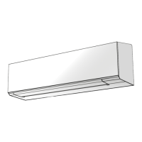
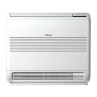
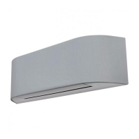
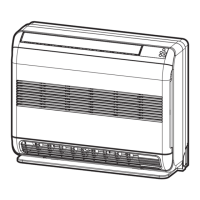
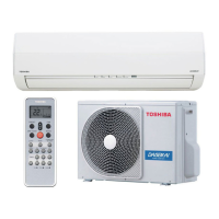
RAS-B05J2KVG-E / RAS-05J2AVG-E
RAS-B07J2KVG-E / RAS-07J2AVG-E
RAS-B1
0J2KVG-E / RAS-10J2AVG-E
RAS-B13J2KVG-E / RAS-13J2AVG-E

 Loading...
