7. REFRIGERANT CYCLE DIAGRAM
7-1. Refrigerant Cycle Diagram
Deoxidized copper pipe
Outer dia. : 9.52mm
Thickness : 0.8mm
NOTE :
Gas leak check position
Refrigerant flow (Cooling)
Refrigerant flow (Heating)
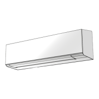
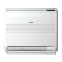
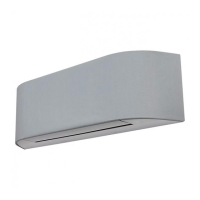
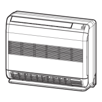
INDOOR UNIT
T1
TO
Temp. measurement
TC
TA
Indoor heat
exchanger
Cross flow fan
Deoxidized copper pipe
Outer dia. : 6.35mm
Thickness : 0.8mm
Sectional shape
of heat insulator
Allowable height
difference : 12m
Allowable pipe length
P
Pressure measurement
Gauge attaching port
Vacuum pump connecting port
Pulse Modulating
valve at liquid side
TD
4-way valve
Compressor
KSK75D43UEZA
TS
T2
Outdoor heat
exchanger
Temp. measurement
Propeller fan
OUTDOOR UNIT
Muffler
Muffler
Min. : 2m
Chargeless : 15m
Strainer
Max. : 15m
Split capillary
TE
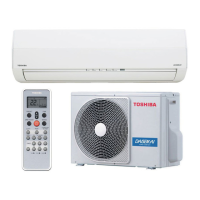
RAS-B05J2KVG-E / RAS-05J2AVG-E
RAS-B07J2KVG-E / RAS-07J2AVG-E
RAS-B10J2KVG-E / RAS-10J2AVG-E
Strainer
05k and 07k Refrigerant amount : 0.40kg
10k Refrigerant amount : 0.43kg

 Loading...
