Do you have a question about the Toshiba RAS-B18G3KVSG-E and is the answer not in the manual?
Explains warning symbols and their meanings for safe operation of the unit.
Specifies required specifications for power supply cords intended for public use.
Critical caution regarding the safe disconnection of the appliance from the main power supply.
Vital safety instructions for qualified personnel, covering electrical work, gas, and overheating hazards.
Important warnings for safe unit modification, installation according to regulations, and refrigerant handling.
Warnings related to unit operation, defrosting, refrigerant properties, and pipe thickness.
Cautions concerning unit exposure to moisture, flammable gases, noise, and proper handling.
Instruction to report appliance installation to the local power supplier before commencing work.
Details on the refrigerant type (R32), its GWP value, and environmental considerations.
Enumerates all accessory parts provided for the indoor unit installation.
Enumerates all accessory parts provided for the outdoor unit installation.
Provides instructions for cleaning and maintaining the unit's air filters.
Visual representation of the installation layout and component placement.
Lists and identifies optional components for specific installation scenarios.
Details on the required specifications for fixing bolts and nuts for the outdoor unit.
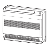
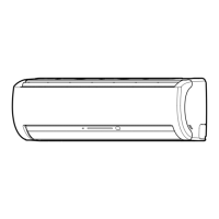
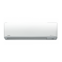
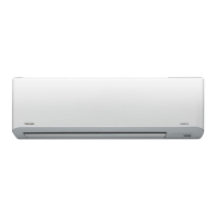
Criteria for selecting an appropriate installation location for the indoor unit.
Recommendations for positioning the remote control for optimal signal reception.
Step-by-step instructions for creating wall openings and securely mounting the installation plate.
Guidelines for insulating connecting pipes and shaping the drain hose correctly.
Specific instructions for connecting refrigerant piping when routed to the left.
Procedures for removing and properly installing the drain hose and cap.
Method for firmly attaching the indoor unit onto the installed wall mounting plate.
Procedures for managing defrost water drainage from the outdoor unit base plate.
Requirements for selecting a suitable location for the outdoor unit, considering environmental factors.
Guidelines for accurately measuring and charging refrigerant into the system.
Special precautions and recommendations for installing the unit in regions with snowfall and cold temperatures.
Steps for installing water-proof caps on the outdoor unit base plate for drainage control.
Detailed instructions on the correct method for flaring refrigerant pipes.
Specifies the required torque values for securely tightening flare pipe connections to prevent leaks.
Step-by-step guide for using a vacuum pump to evacuate air and moisture from the system.
Essential precautions and techniques for safely operating and handling packed valves.
Detailed sequence of operations required to perform the pump down process correctly.
General guidance on selecting power sources and connecting electrical cables.
Specific instructions for wiring the indoor unit, including terminal connections.
Specific instructions for wiring the outdoor unit, including terminal connections.
Procedure for installing the air inlet grille on the indoor unit after wiring.
Wiring diagram for recommended power supply input at the outdoor unit's terminal block.
Wiring diagram for optional power supply input at the indoor unit's terminal block.
Visual diagram illustrating the recommended power supply wiring for the outdoor terminal block.
Visual diagram illustrating the optional power supply wiring for the indoor terminal block.
Critical safety warnings and guidelines to follow during electrical wiring connections.
Power supply input wiring diagram specifically for the outdoor terminal block in an IMS setup.
Overall wiring diagram for connecting the power supply in an Inverter Multi System (IMS).
Key cautions and safety measures to observe during the electrical installation of an IMS unit.
Step-by-step instructions for conducting a gas leak test on the installed system.
Instructions on how to perform a test run to verify system functionality.
Details on how to enable or disable the auto restart feature after a power interruption.
Procedure for setting remote controls to A or B for managing multiple indoor units.
Basic conditions and work instructions for assessing and reusing existing refrigerant pipes.
Identifies specific conditions under which existing pipes must not be reused and require replacement.
Procedures for curing pipes and a decision-making guide for determining reuse suitability.
Information on necessary adjustments to flare nut width and machining size for existing pipes.
| Cooling Capacity | 5.0 kW |
|---|---|
| Heating Capacity | 5.8 kW |
| Energy Efficiency Ratio (EER) | 3.21 |
| Refrigerant | R32 |
| Power Supply | 220-240V, 50Hz |
| Coefficient of Performance (Heating) | 3.61 |
| Outdoor Unit Noise Level | 49 dB(A) |
| Type | Split Type |