Do you have a question about the Toshiba RAS-B18UFV-E and is the answer not in the manual?
Explanations of indications, illustrated marks, and guidelines for public use.
Precautions for R410A refrigerant and its installation requirements.
DANGER, WARNING, and CAUTION statements regarding installation and servicing procedures.
Notes on heating operation, drainage difficulties, and handling sharp edges.
Detailed technical specifications for indoor and outdoor units, including electrical characteristics.
Information on outdoor units compatible with B**UFV-E series indoor units.
Graphs showing current vs. compressor speed for cooling and heating operations.
Charts detailing capacity changes based on outdoor temperature for cooling and heating.
Essential safety precautions when handling R410A refrigerant during installation and servicing.
Guidelines for selecting and installing piping materials, joints, and their thicknesses.
Procedures and precautions for cutting and preparing piping materials.
Steps and considerations for connecting flare joints, including tightening torque.
List of tools specifically needed for R410A installation and their interchangeability.
Step-by-step procedure for recharging refrigerant, including cautions.
Types of brazing fillers and their applications for joining copper pipes.
Detailed steps for brazing pipes, including preventing oxidation and safety warnings.
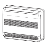
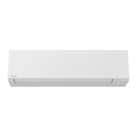
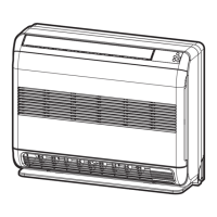
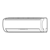
Diagrams showing the internal and external structure of the indoor unit.
Dimensional drawings and views of the outdoor unit.
Dimensional drawings and views of the outdoor unit RAS-18SAV-E.
Electrical wiring schematic for specific indoor and outdoor unit models.
Electrical wiring schematic for specific indoor and outdoor unit models.
List of electrical components and their specifications for the indoor unit.
List of electrical components and their specifications for the outdoor unit.
Schematic illustrating the refrigerant flow and components for specific models.
Schematic illustrating the refrigerant flow and components for specific models.
Table showing operational parameters (pressure, temperature, fan speed, compressor speed).
Diagram showing the internal control logic and signal flow of the indoor unit.
Diagram illustrating the control logic and components of the outdoor unit inverter assembly.
Overview of the air conditioner's control system, including indoor and outdoor unit roles.
Functions performed by the indoor unit controller.
Functions performed by the outdoor unit controller.
List of detailed operational descriptions, from basic operation to specific modes.
Flowchart and data related to basic operation control of indoor and outdoor units.
Description of cooling and heating operation control logic.
Details on how the auto operation mode functions based on room temperature.
Description of DRY operation, including temperature differences and fan speed control.
Explanation of indoor fan speed control in cooling mode, including symbols and table.
Explanation of indoor fan speed control in heating mode, including figures and control logic.
Table detailing indoor fan speeds and air flow rates for heating operation.
Control logic for the outdoor fan motor based on temperature and compressor speed.
Table showing outdoor fan speeds (RPM) for different models and conditions.
How cooling/heating capacity is adjusted based on temperature differences and compressor revolution.
Function to prevent compressor drive circuit from exceeding specified values.
Control logic to prevent freezing (cooling) or overpressure (heating) based on heat exchanger temperature.
Procedure for removing frost from the outdoor heat exchanger using 4-way valve reverse defrost.
How to change air outlet direction and cancel settings.
How to open or close the lower louver and its operation during use.
How to set and store the upper louver position, with diagrams showing angles.
Description of the economic operation mode for cooling and heating.
Procedure to perform temporary cooling operation for testing.
How compressor speed is controlled based on discharge temperature for error detection and protection.
Function of the P.M.V. in controlling refrigerant flow and its operation during different modes.
Purpose and operation of the self-cleaning function to keep the indoor unit clean.
Diagram showing the operational states of the self-cleaning function.
Procedures to set and cancel the self-cleaning function.
How to set the remote control to operate a specific indoor unit in multi-unit installations.
Operation to reduce indoor fan speed for quieter performance.
Function to save energy and improve comfort during sleep.
How to use the short timer for immediate unit startup or testing.
Fully automated operation based on regional preferences.
Operation to increase cooling or heating performance.
How the filter indicator works and how to reset it after cleaning.
How to adjust the set temperature to compensate for room temperature differences.
Function to reduce compressor revolution for quieter outdoor unit operation.
How to set and cancel the outdoor quiet control.
Function to automatically restart the unit after a power failure.
Step-by-step guide to enable the auto restart function.
Procedure to disable the auto restart function.
How power failures affect timer operations.
Overview of buttons and functions on the remote control.
Basic operation modes like ONE-TOUCH, AUTO, COOL/HEAT.
Details on DRY, Hi-POWER, FLOOR WARMING, and ECO operations via remote control.
Description of PRESET, AUTO RESTART, QUIET, COMFORT SLEEP, and SLEEP TIMER operations.
How to reset the filter indicator after cleaning.
Explanation of the self-cleaning function for cooling and dry modes.
General notes on operation, preheating, warm air control, defrosting, and sounds.
Table of common troubleshooting checks for unit operation issues.
Procedure to select remote control A or B for multi-unit installations.
How to adjust the brightness of the indoor unit display panel.
How to change the air outlet grille setting during stable cooling operation.
Instructions for cleaning the air inlet grille.
Explanation of all indicators shown on the remote control display.
Explanation of the indicators and buttons on the indoor unit's operation panel.
Diagram showing placement and clearances for indoor and outdoor units.
List and description of optional parts for installation, like piping and insulation.
List of included accessories and installation parts such as remote control, batteries, and screws.
Comparison of new tools required for R410A and their changes from R22 models.
Guidelines for selecting an appropriate location to install the indoor unit.
Procedures for cutting holes and mounting the installation plate for the indoor unit.
Steps for removing front panel, air inlet grille, and wiring connections.
Instructions for proper drain pipe routing and electrical wiring.
Special method for installing the indoor unit recessed into a wall.
Instructions for mounting the indoor unit directly on the floor or a wall.
Criteria for selecting an appropriate location for the outdoor unit.
Installation considerations for regions with snow and cold weather.
Steps and specifications for flaring refrigerant pipes.
How to drain water from the outdoor unit using drain nipples and caps.
Steps for evacuating air and moisture from the refrigerant circuit.
Instructions for connecting electrical wires between indoor and outdoor units.
Safety and wiring standards for electrical connections.
Procedure to check for refrigerant gas leaks after installation.
How to set the remote control selector switch for multi-unit operation.
Procedure for selecting remote control A or B for specific indoor units.
General procedures and precautions for diagnosing troubles.
Safety warnings and precautions for working with the 3DV inverter.
Warnings and procedures for safely handling high-voltage circuits and discharging capacitors.
Notes and methods for inspecting the outdoor unit's control section, including capacitor discharging.
Checks for power supply, voltage, and normal program operations.
Table describing normal operations that might be mistaken for troubles.
Methods for diagnosing troubles, starting with LED flashing.
Table of indoor unit LED flashing codes and their corresponding error descriptions.
How to perform self-diagnosis using the remote controller and check codes.
Steps for entering and exiting the remote controller's service mode.
Table detailing causes and actions for various block distinctions and check codes.
Continues the table of check codes, causes, and actions for outdoor unit and other errors.
Continues the table of check codes for compressor and 4-way valve errors.
General approach to diagnosing issues based on observed symptoms.
Troubleshooting steps for when the indoor unit does not turn on at all.
Troubleshooting steps for when the indoor fan motor does not operate or operates incorrectly.
Explanation of why the indoor fan motor might auto-rotate and how to check it.
Flowchart for diagnosing issues related to the remote control and its communication.
Troubleshooting steps for issues related to interconnecting and serial signal wiring.
Diagnostic procedures for miswiring and discharge temperature/gas leak errors.
Summarized diagnostic flow for the outdoor unit's inverter assembly.
General procedures for checking main components.
Steps for inspecting the indoor unit's P.C. board for defects.
Detailed check procedures for fuses, power supply, indicators, compressor, and fan motor.
Diagram showing the layout of components on the P.C. board.
Table showing resistance values of various sensors at different temperatures.
Checking resistance values for indoor unit components like sensors, motors, and remote control.
Checking resistance values for outdoor unit components like compressor, fan motor, and coils.
Detailed checking procedures for capacitors and diode blocks.
Steps to determine if the outdoor fan motor is good or bad, including resistance checks.
General safety warnings and procedures for replacing main parts.
Step-by-step guide to remove and replace the front panel of the indoor unit.
Procedure for removing and replacing the electrical parts box (E-box) from the indoor unit.
Procedure for removing and replacing the heat exchanger assembly.
How to open and adjust the horizontal louver.
Procedure for removing and replacing the louver base assembly.
How to remove and replace the bell mouth and drain pan.
Steps to remove and replace the turbo fan and fan motor.
Continues the procedure for removing the fan motor, including flange nut and lead cover.
Procedure for replacing the microcomputer and associated components.
Steps for detaching and attaching the upper cabinet and valve cover of the outdoor unit.
Procedure for removing and attaching the front cabinet of the outdoor unit.
Steps for replacing the inverter assembly, including safety precautions for high voltage.
Procedure for disconnecting and replacing the control board assembly.
Steps to remove and replace the right and left side cabinets of the outdoor unit.
Procedure for removing and replacing the fan motor, including flange nut and propeller.
Detailed steps for removing and replacing the compressor, including refrigerant extraction and pipe disconnection.
Procedure for removing and replacing the reactor.
Steps to remove and attach the electronic expansion valve coil.
Procedure for removing and attaching the fan guard.
Instructions for installing TE, TS, TD, and TO sensors on the outdoor unit.
Exploded view diagram of the indoor unit and its parts list.
Exploded view diagram of the indoor unit's E-parts and their list.
Exploded view diagram of the outdoor unit and its parts list.
Exploded view diagram of the outdoor unit and its parts list.
Diagram showing the layout of components on the P.C. board for specific models.
Diagram showing the layout of components on the P.C. board for a specific model.
Diagram showing the layout of components on the P.C. board for a specific model.
| Energy Efficiency Ratio (EER) | 3.21 |
|---|---|
| Seasonal Energy Efficiency Ratio (SEER) | 6.1 |
| Coefficient of Performance (COP) | 3.61 |
| Power Supply | 220-240V, 50Hz |
| Refrigerant | R32 |
| Noise Level (Outdoor) | 52 dB(A) |
| Type | Split System |
| Outdoor Unit Dimensions (W x H x D) | 780 x 550 x 290 mm |
| Operating Temperature (Heating) | -15 to 24°C |
| Cooling Capacity | 18000 BTU/h |