– 97 –
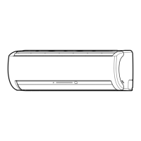
11-9-3. Indoor Unit (Other Parts)
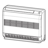
11-9-4. Outdoor Unit
No.
1
Part name
Room temp. (TA) sensor
Heat exchanger (TC) sensor
Heat exchanger (TCJ) sensor
Checking procedure
Disconnect the connector and measure the resistance value with tester.
(Normal temp.)
No.
1
Part name
Compressor
(Model : DA150A1F-20F)
Checking procedure
Measure the resistance value of each winding by using the tester.
Measure the resistance value of winding by using the tester.
Red
White Blac
Check conduction
by using the tester.
Disconnect the connector, and measure resistance value with the tester.
(Normal temperature)
5
4
3
2
1
White
Yellow
Yellow
Yellow
Yellow
5
4
3
2
1
Refer to 11-4-1. (5).
Measure the resistance value of each winding coil by using the tester.
(Under normal temp. 25°C)
Refer to 11-4-1. (3) and (4).
2
3
Remote controller
Louver motor
MP24Z3N
4 Indoor fan motor
Under 20°C
Position
Yellow - Pink
Resistance value
5 to 20 kΩ
2
3
4
Outdoor fan motor
(Model : ICF-140-63-2R)
Compressor thermo.
Bimetal type
(Model : US622KXTMQO)
Outdoor temperature sensor
(TO), pipe temperature
sensor (TGa, TGb, TGc,
TGd), discharge tempera-
ture sensor (TD), suction
temperature sensor (TS)
*
,
evaporator temperature
sensor (TE)
*
*
: Heat pump model only
For details, refer to Section 11-5.
Red
1 Yellow
4 Pink
5 Gray
White Black
Temperature
Sensor
TA, TC, TCJ (kΩ)
10°C 20°C 25°C 30°C 40°C
20.7 12.6 10.0 7.9 4.5
Position
1 to 2
1 to 3
1 to 4
1 to 5
Resistance value
250 ± 20 Ω
Position
Red - White
White - Black
Black - Red
Resistance value
0.93 ± 0.05 Ω
Temperature
Sensor
TO, TE, TS (kΩ)
TGa, TGb, TGc, TGd (kΩ)
10°C 20°C 25°C 40°C 50°C
20.6 12.6 10.0 5.1 3.4
20.0 12.5 10.0 5.3 3.6
Operation
OFF
ON
Operating temperature
125 ± 4°C
90 ± 5°C

 Loading...


