Do you have a question about the Toshiba RAS-B22N3KV2-E and is the answer not in the manual?
Detailed technical specifications for indoor and outdoor units.
Graphical representation of cooling/heating current vs. compressor speed.
Graph showing cooling/heating capacity changes with outdoor temperature.
Precautions for handling R410A refrigerant during installation and servicing.
Guidelines for installing refrigerant piping using copper pipes and joints.
Information on suitable copper pipes, flare joints, and socket joints for R410A.
Steps and precautions for cutting, deburring, and flaring pipes.
Detailed dimensions and procedures for R410A flare processing.
How to correctly connect flare joints and tightening torque values.
List of tools specifically required for R410A refrigerant handling and installation.
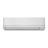
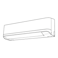
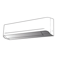
Diagrams showing the dimensions and parts of the indoor unit.
Diagrams showing the dimensions and parts of the outdoor unit.
Schematic showing electrical connections between indoor and outdoor units.
Diagram illustrating the control functions and signals within the indoor unit.
Diagram showing the control functions and signals within the outdoor unit.
Overview of the air conditioner's control system and components.
Detailed flow of operation control based on remote controller input and unit status.
How the unit operates in cooling and heating modes based on signals.
How the unit automatically selects operating mode based on room temperature.
How the unit operates in DRY mode based on temperature difference.
How the indoor fan speed is controlled in manual and auto modes.
How the outdoor fan speed is controlled based on compressor speed and temperature.
How cooling/heating capacity is adjusted by compressor revolution based on temperature.
Function to prevent inverter part troubles and control compressor speed.
Prevent-freezing control in cooling and prevent-overpressure control in heating.
How frost on the outdoor heat exchanger is removed using a 4-way valve.
How the indoor unit controls the louver position and swing for air direction.
Energy-saving operation mode that adjusts temperature and compressor speed.
How to start/stop operation using the RESET button without the remote.
How compressor speed is controlled based on discharge temperature to prevent errors.
How the PMV controls refrigerant flow based on super heat and discharge temperature.
Operation to dry the indoor unit to prevent mold and bacteria growth.
How to set the remote controller to operate a specific indoor unit.
Operation that restricts indoor fan speed for quieter operation.
Operation to save energy and improve comfort during sleep.
Purpose and setting of the short timer for unit testing or trial.
Fully automated operation set according to regional preferences.
Operation mode for faster cooling by increasing fan speed and lowering temperature.
Indicator for filter cleaning reminder and how to turn it off.
How to set the unit to restart with previous settings after power failure.
Explanation of remote controller buttons and their basic functions.
How to use various functions like ONE-TOUCH, AUTO, and COOLING/HEATING.
Explanation of the display indicators and symbols on the remote controller.
Visual guide showing the placement and connections for indoor and outdoor units.
List of optional parts, accessories, and tools required for installation.
Details on new tools required for R410A systems and their differences from R22.
Criteria for selecting a suitable location for the indoor unit installation.
Procedures for cutting holes and mounting the indoor unit's installation plate.
Steps for connecting the power cord and connecting cable to the indoor unit.
Instructions for connecting the remote controller via wire.
Guidance on forming and installing refrigerant pipes and drain hoses.
Criteria for selecting an appropriate location for the outdoor unit installation.
How to flare pipes and connect them securely according to R410A specifications.
Procedure for removing air from the refrigerant pipes using a vacuum pump.
Steps for connecting electrical wiring to the outdoor unit.
How to check for refrigerant gas leaks after installation.
How to set remote control for multi-indoor unit systems.
How to perform a test run to confirm proper installation and operation.
How to set the unit to restart with previous settings after power failure.
A table outlining the steps for diagnosing and troubleshooting unit issues.
Safety warnings and precautions for working with the inverter unit.
Safety measures for inspecting the outdoor unit's control section, especially regarding high voltage.
Initial checks for power supply and voltage before diagnosing issues.
Methods for initial troubleshooting, including LED indicators and symptoms.
Interpreting flashing LED codes on the indoor unit for self-diagnosis.
How to use the remote controller in service mode to retrieve check codes for diagnosis.
Troubleshooting flowcharts based on specific unit symptoms like no operation.
Diagnosing issues related to wiring faults between indoor and outdoor units.
Specific check codes and procedures for miswiring and discharge temperature errors.
Step-by-step guide for diagnosing problems within the outdoor unit.
Procedures for checking key components like P.C. boards and sensors.
Method to test the outdoor fan motor's functionality and diagnose potential errors.
Procedures for disassembling and replacing parts of the indoor unit.
Steps to remove and install the indoor unit's electric parts box assembly.
Procedure for removing and installing the horizontal louver of the indoor unit.
Steps for removing and installing the indoor unit's evaporator (heat exchanger).
Procedure for removing and installing the bearing for the indoor unit fan.
Steps for removing and installing the indoor unit's fan motor.
Cautionary notes and procedures for reassembling the cross flow fan.
Procedures for disassembling and replacing parts of the outdoor unit.
Steps for removing and installing the outdoor unit's inverter assembly, including safety precautions.
Procedures for disconnecting and replacing the outdoor unit's control board assembly.
Steps for removing and installing the right and left side cabinets of the outdoor unit.
Procedure for removing and installing the outdoor unit's fan motor.
Steps for removing and installing the compressor, including refrigerant extraction.
Procedure for removing the reactors from the outdoor unit.
Instructions for installing temperature sensors (TE, TS, TD, TO) on the outdoor unit.
Detailed breakdown of indoor unit parts with corresponding part numbers.
Exploded view and parts list for specific indoor unit components.
Detailed breakdown of outdoor unit parts with corresponding part numbers.
Diagram showing the layout of the outdoor unit's P.C. board for a specific model.
Diagram showing the layout of the outdoor unit's P.C. board for another specific model.
| Type | Split System |
|---|---|
| Cooling Capacity | 2.2 kW |
| Heating Capacity | 2.5 kW |
| Refrigerant | R32 |
| Power Supply | 220-240V, 50Hz |
| Energy Efficiency Ratio (EER) | 3.21 |
| Coefficient of Performance (COP) | 3.61 |
| Indoor Unit Weight | 9 kg |