EasyManua.ls Logo

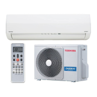
Toshiba RAS-B10BKVG-E User Manual

Toshiba RAS-B10BKVG-E
17 pages
To Next Page IconTo Next Page
Page #1 background imageLoading...
Page #1 background image
AIR CONDITIONER (SPLIT TYPE)
INSTALLATION MANUAL
Indoor unit
RAS-B05, 07, 10, 13, 16BKVG-E
Outdoor unit
RAS-05, 07, 16BAVG-E
RAS-10, 13BAVG-E1
1122950197
R32
ENGLISH
ESPAÑOL
FRANÇAIS
ITALIANO
DEUTSCH
PORTUGUÊS
POLSKI
ČESKY
PУCСКИЙ
HRVATSKI
MAGYAR
NEDERLANDS
ΕΛΛΗΝΙΚΑ
SVENSKA
SUOMI
NORSK
DANSK
ROMÂNĂ
БЪЛГАРСКИ
EESTI
LATVISKI
SLOVENČINA
SLOVENŠČINA
LIETUVIŲ
Question and Answer IconNeed help?

Do you have a question about the Toshiba RAS-B10BKVG-E and is the answer not in the manual?

Toshiba RAS-B10BKVG-E Specifications

General IconGeneral
BrandToshiba
ModelRAS-B10BKVG-E
CategoryAir Conditioner
LanguageEnglish

Summary

PRECAUTIONS FOR SAFETY

Main Power Disconnection Caution

Instructions for safely disconnecting the appliance from the main power supply.

Critical Danger Warnings

Essential safety warnings for qualified personnel regarding electrical work and risks.

Refrigerant Handling and Leak Risks

Warnings on mixing gases with refrigerant and handling leaks to prevent injury.

INSTALLATION DIAGRAM OF INDOOR AND OUTDOOR UNITS

INDOOR UNIT INSTALLATION

OUTDOOR UNIT INSTALLATION

Refrigerant Piping Flaring Procedure

Detailed steps and specifications for performing flare connections on refrigerant pipes.

Flare Connection Tightening Procedure

Instructions for tightening flare pipe connections to specified torque values.

Flare Pipe Tightening Torque Specifications

Table detailing the correct tightening torques for various pipe sizes.

Evacuating the Refrigerant System

Steps for evacuating air from connecting pipes using a vacuum pump.

ELECTRICAL WORKS

Indoor Unit Wiring Instructions

Step-by-step guide for wiring the connecting cable to the indoor unit.

Outdoor Unit Wiring Instructions

Step-by-step guide for wiring the power and connecting cables to the outdoor unit.

1:1 UNIT WIRING DIAGRAMS

1:1 UNIT POWER SUPPLY WIRING

Indoor Terminal Block Power Input Diagram

Wiring diagram for power input at the indoor unit terminal block.

Critical Electrical Installation Cautions

Essential electrical safety precautions for installation and wiring.

INVERTER MULTI SYSTEM (IMS) WIRING

IMS Electrical Safety Cautions

Electrical safety precautions specific to multi-system installations.

ADDITIONAL INSTALLATION PROCEDURES

Gas Leak Test Procedure

Steps for performing a gas leak test on the connected refrigerant piping.

APPENDIX AND PIPE REUSE

Reusing Existing Refrigerant Pipes

Conditions and checks required for reusing existing R22/R410A pipes for R32.

Related product manuals