Do you have a question about the Toshiba RAS-M13NKCV-E and is the answer not in the manual?
Electrical and physical specifications for specific indoor unit models.
Electrical and physical specifications for specific indoor unit models.
Detailed diagram showing dimensions and component placement of the indoor unit.
Electrical wiring schematic for 10k and 13k capacity indoor units.
Step-by-step guide for basic troubleshooting of common issues.
Electrical wiring schematic for 16k capacity indoor units.
List and specifications of electrical components for specific indoor unit models.
List and specifications of electrical components for specific indoor unit models.
Diagram illustrating the functional blocks and signal flow within the indoor unit.
Details on how the remote controller interacts with different indoor unit models.
Explains the overall control architecture and interaction between indoor and outdoor units.
Details the responsibilities and functions of the indoor unit's control board.
Details the responsibilities and functions of the outdoor unit's control board.
How cooling capacity is controlled by compressor motor speed.
Describes the process to prevent indoor heat exchanger freezing in cooling mode.
Details how compressor speed is reduced when current exceeds limits.
How current release points are adjusted based on outdoor temperature.
Details the SUL fan speed in starting and stability conditions.
Describes how heating capacity is controlled based on room temperature.
Explains how compressor speed is reduced at high indoor heat exchanger temperatures.
Details how compressor speed is reduced based on current input.
Explains how operation mode is selected based on outside temperature.
Conditions under which the operation mode can be re-selected.
Details the Powerful Cool mode operation and louver direction.
Explains how to start and operate Temporary Auto mode.
Explains how to start and operate Temporary Cooling mode.
Step-by-step instructions on how to enable the auto restart feature.
Step-by-step instructions on how to disable the auto restart feature.
Explains cancellation of timer operation due to power failure.
Information about the filter check lamp and its reset procedure.
Explains the purpose and operation of each button on the remote control.
Important safety warnings and guidelines to follow during installation.
Specific instructions and precautions for installing units using R-410A refrigerant.
Steps for installing the wireless remote control holder and batteries.
Instructions on proper insulation of refrigerant pipes.
Guidelines for selecting an appropriate location for the indoor unit.
Recommendations for positioning the remote controller for optimal signal reception.
Instructions for securely mounting the indoor unit's installation plate.
Step-by-step guide for connecting the indoor unit's power and control cables.
Instructions for forming and installing refrigerant pipes and the drain hose.
Instructions for configuring the remote controller selector switch on the indoor unit.
Instructions for configuring the remote controller selector switch on the remote control.
Basic checks to perform before detailed troubleshooting.
Identifies operational behaviors that are not considered equipment malfunctions.
Outlines the initial methods for diagnosing issues, starting with LED indicators.
Step-by-step guide to activate service mode on the remote control for diagnostics.
Procedures for inspecting the indoor unit's P.C. board for defects.
Procedures for removing and replacing main components of the indoor unit.
Step-by-step instructions for replacing the heat exchanger assembly.
Procedures for removing and replacing the cross flow fan and motor.
Instructions for replacing the base bearing for the fan motor.
Exploded diagram and list of electronic parts (E-Parts Assy) for the indoor unit.
| Type | Split System |
|---|---|
| Cooling Capacity | 3.5 kW |
| Heating Capacity | 4.0 kW |
| Refrigerant | R410A |
| Power Supply | 220-240V, 50Hz |
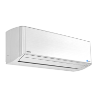
| Indoor Unit Dimensions (W x H x D) | 798 x 293 x 230 mm |
| Outdoor Unit Dimensions (W x H x D) | 780 x 550 x 290 mm |
| Indoor Unit Weight | 9 kg |
| Outdoor Unit Weight | 30 kg |
| Noise Level (Outdoor) | 50 dB(A) |