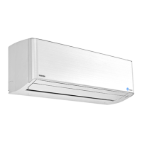
Do you have a question about the Toshiba RAS-M13U2DVG-E and is the answer not in the manual?
Details safety precautions for handling R410A and R32 refrigerants during installation and service.
Covers requirements and procedures for installing refrigerant piping, including materials and joints.
Details various operation modes, fan control, capacity control, and specific functions like auto restart.
Covers installation procedures, external dimensions, hanging bolt installation, and handling precautions for the unit.
Provides guidelines for refrigerant piping, including permissible length, pipe size, flaring, and airtight testing.
Explains the electrical connection requirements, wiring diagrams, and optional wired remote controller wiring.
Outlines initial checks for power supply and voltage to confirm basic operation readiness.
Details the procedure for using the remote controller in service mode to perform self-diagnosis and read check codes.
Provides symptom-based troubleshooting procedures for indoor unit issues like no power or fan not operating.
| Cooling Capacity | 3.5 kW |
|---|---|
| Heating Capacity | 4.0 kW |
| Refrigerant | R32 |
| Power Supply | 220-240V, 50Hz |
| Indoor Unit Dimensions (W x H x D) | 798 x 293 x 230 mm |
| Outdoor Unit Dimensions (W x H x D) | 780 x 550 x 290 mm |
| Type | Split |
| Coefficient of Performance (COP) | 4.0 |


 Loading...