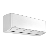
Do you have a question about the Toshiba RAS-M13YKV-E and is the answer not in the manual?
Details on unit specifications, capacities, noise, dimensions, and piping.
Performance data for various indoor/outdoor unit combinations, including capacity and power consumption.
Electrical specifications for outdoor units, including MCA, MOCP, FLA, and voltage ranges.
Precautions and safety guidelines for handling R410A refrigerant during installation and servicing.
Details on piping materials, joints, and processing for R410A refrigerant systems.
Lists required and general tools for R410A installation and servicing, noting interchangeability.
Step-by-step procedure for safely recharging refrigerant into the system, including precautions.
Guidelines for materials, flux, and brazing procedures, emphasizing safety and preventing oxidation.
Exploded view and dimensions of the indoor unit and its components.
Exploded view and dimensions of the outdoor unit and its components.
Wiring diagram for the indoor unit, including simple check points for fault diagnosis.
Wiring diagram for the outdoor unit, showing connections for various components and boards.
List of electrical parts used in the indoor unit with their specifications.
List of electrical parts used in the outdoor unit with their specifications.
Control block diagram of the indoor unit, detailing MCU functions and remote controller signals.
Control block diagram of the outdoor unit, including inverter assembly and MCU functions.
Overview of air conditioner control system, indoor/outdoor unit controller roles, and compressor control.
How cooling capacity is controlled by varying compressor motor speed.
How outdoor unit controls compressor speed to prevent exceeding current limits.
How the system prevents freezing of the indoor heat exchanger by reducing compressor speed.
Function of the Pulse Modulating Valve in controlling refrigerant flow.
Control of vertical air flow louvers, including auto and manual settings.
Control of indoor fan motor speed and air flow rates.
Explanation of the operation circuit and fan-only mode.
Detailed description of cooling operation, including capacity and temperature controls.
Description of the DRY operation mode, focusing on dehumidification.
Description of heating operation, including capacity control and defrost.
How to use temporary operation modes like Auto and Cooling.
Functionality and setting procedures for automatic restart after power interruption.
Step-by-step instructions for enabling the auto restart function.
Procedure to disable or cancel the auto restart function.
Critical safety warnings and precautions for installation, including electrical and refrigerant handling.
Detailed procedures for installing the indoor unit.
Guidelines for selecting an appropriate installation location for the indoor unit.
Instructions for cutting wall holes and mounting the installation plate for the indoor unit.
Procedures for connecting inter-connect cables and wiring, including grounding.
Steps for installing refrigerant piping and drain hoses for the indoor unit.
Proper methods for running and installing the drain hose to ensure correct drainage.
Steps to securely fix the indoor unit onto the installation plate.
How to set the remote controller selector switch for multi-indoor unit installations.
Procedures for checking and testing the installed unit's operation.
Procedures for installing the outdoor unit.
Specific requirements for refrigerant piping kits and materials for R410A.
Guidelines for selecting an appropriate installation location for the outdoor unit.
Detailed instructions for connecting refrigerant piping, including flaring and tightening.
General installation notes for the outdoor unit, including clearance and securing.
Procedure for evacuating air from the refrigerant system using a vacuum pump.
Instructions for connecting the power cord and wiring to the outdoor unit.
Steps for checking connections and testing the system after installation.
Procedure to check for incorrect wiring and piping using LED indicators.
Initial confirmation steps including power supply and voltage checks.
Initial troubleshooting steps using flashing LEDs, remote controller self-diagnosis, and symptom analysis.
Interpreting indoor unit LED indications to diagnose protective circuit operations.
Using the remote controller to perform self-diagnosis and retrieve error codes.
Troubleshooting symptoms related to the indoor unit, outdoor unit, and wiring.
Interpreting outdoor unit LED indications for self-diagnosis of faults.
A flowchart for diagnosing inverter assembly issues in the outdoor unit.
Procedures for checking main electrical parts like P.C. boards, sensors, and motors.
Step-by-step guide to test the outdoor fan motor's functionality.
Procedures for replacing major indoor unit components like the front panel and electrical parts.
Layout and replacement of the microcomputer and its associated P.C. board.
Procedures for detaching and replacing major outdoor unit components like the inverter, control board, and compressor.
Exploded view and parts list for the indoor unit (part 1).
Exploded view and parts list for the outdoor unit, including model numbers.
Layout of P.C. boards and sensor connections for the RAS-4M27YAV-E outdoor unit.
| Brand | Toshiba |
|---|---|
| Model | RAS-M13YKV-E |
| Category | Air Conditioner |
| Language | English |


 Loading...