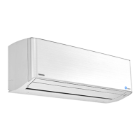
Do you have a question about the Toshiba RAS-M13SKV-E and is the answer not in the manual?
Covers general safety, refrigerant handling, electrical safety, installation warnings, and cautions.
Details outdoor unit combinations with indoor units for heat pump and cooling types.
Safety measures for R410A handling during installation and servicing to prevent hazards.
Details specific requirements and procedures for piping materials used with R410A.
Lists the specialized tools necessary for working with R410A refrigerant systems.
Covers procedures for charging refrigerant and brazing pipes, including materials and techniques.
Illustrates the internal and external structure of the indoor unit with dimensions.
Provides schematic diagrams for connecting electrical components of indoor and outdoor units.
Lists specifications for indoor unit components like fan motor, sensors, and louver motor.
Illustrates the flow of refrigerant through the indoor and outdoor units.
Shows the control logic and signal flow for the indoor unit and remote controller.
Overview of the control system, roles of indoor/outdoor units, and signal communication.
Details basic operation, fan motor control, capacity control, and protective functions.
Details Auto Restart function, Remote Control operations, and indications.
Describes intermittent operation of indoor fans during heating in multi-room configurations.
Illustrates the installation setup for indoor and outdoor units.
Lists optional installation parts, accessories, and tools required for installation.
Details installation and servicing tools, highlighting changes for R410A.
Guides on location, drilling, electrical, wiring, piping, and drain hose setup for the indoor unit.
Steps for initial checks and primary methods to diagnose potential issues with the unit.
Diagnosing issues based on indoor unit LED flashing patterns and check codes.
Guides diagnosing troubles based on specific symptoms like power issues or fan motor problems.
Identifies and diagnoses issues related to wiring failures, including interconnecting and serial signal wires.
Procedures for removing and reassembling the indoor unit's front panel.
Steps for replacing the electric parts box, sensors, and related components.
Instructions for replacing the horizontal louver, evaporator (heat exchanger), and bearing.
Procedures for replacing the microcomputer and related P.C. board components.
Provides exploded diagrams and a list of parts for the indoor unit.
| Brand | Toshiba |
|---|---|
| Model | RAS-M13SKV-E |
| Category | Air Conditioner |
| Language | English |


