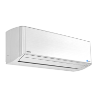
Do you have a question about the Toshiba RAS-M13SKCV-E and is the answer not in the manual?
Important safety instructions for installation, servicing, and general use.
Details on combined outdoor units for heat pump and cooling-only types.
Electrical characteristics, noise, dimensions, and accessories for indoor units.
Dimensions, weight, compressor, and fan specs for outdoor units.
Details on piping connections, lengths, and wiring requirements.
Specifications specific to cooling-only indoor and outdoor units.
Safety precautions specific to R410A installation and servicing.
Guidelines for installing and processing R410A piping materials.
Procedures and precautions for connecting flare joints.
Lists exclusive and general tools required for R410A installation.
Step-by-step guide for recharging refrigerant, including cylinder usage.
Materials, flux, and brazing methods to prevent oxidation.
Diagrams showing indoor unit dimensions and parts like air filter, heat exchanger.
Dimensions for installation plate, remote control holder, and piping connections.
Electrical wiring diagrams for various RAS-M10/13SKV/SKCV models.
Electrical wiring diagrams for RAS-M16SKV/SKCV models.
Specifications for indoor unit components like fan motor, sensors, and louver motor.
Diagram showing the refrigerant flow within the indoor unit.
Block diagram illustrating the control functions of the indoor unit.
Control block diagram for cooling-only indoor units.
Outlines the control system, roles of indoor/outdoor units, and signal communication.
Covers basic operation, AUTO, DRY, ECO, and temporary modes.
Details on controlling fan speed, louver direction, and unit capacity.
Explains Self-Cleaning, Quiet, Comfort Sleep, and Timer functions.
Guide to operating the remote control for various functions and indicators.
How indoor fans operate intermittently during heating thermo-off.
Visual guide for unit installation and remote controller battery loading.
Lists optional parts, accessories, and special tools for installation.
Guidelines for unit placement, drilling, mounting plate, and wiring.
Procedures for forming pipes, drain hose, and attaching caps.
Requirements for electrical work and connecting the unit's cable.
Basic checks for power, voltage, and normal operation patterns.
Overview of diagnosis methods: LED, remote controller self-diagnosis, symptoms.
Table for interpreting indoor unit LED flashing codes for self-diagnosis.
Using the remote controller in service mode to diagnose issues.
Step-by-step guides for common symptoms like no power or fan issues.
Diagnosing issues related to wiring, interconnecting, and serial signals.
Safety warnings and precautions before starting part replacement.
Procedures for disassembling the indoor unit, including front panel and parts.
Steps for replacing electric parts box, louver, evaporator, motor, and bearing.
Layout and checks for the microcomputer and P.C. board.
Exploded view and parts list for the indoor unit components.
| Type | Split System |
|---|---|
| Cooling Capacity | 3.5 kW |
| Heating Capacity | 4.0 kW |
| EER | 3.21 |
| Refrigerant | R410A |
| Power Supply | 220-240V, 50Hz |
| Indoor Unit Dimensions (HxWxD) | 293x798x230 mm |
| Outdoor Unit Dimensions (HxWxD) | 550x780x290 mm |
| Noise Level (Outdoor Unit) | 50 dB(A) |
| Indoor Unit Weight | 9 kg |
| Noise Level (Indoor Unit) | 42 dB(A) |


