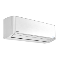
Do you have a question about the Toshiba RAS-M13NKV-E and is the answer not in the manual?
Detailed diagrams illustrating the construction and dimensions of the indoor unit.
Wiring diagrams for indoor units, including for 10k/13k and 16k models.
Detailed specifications for electrical components used in specific indoor unit models.
Detailed specifications for electrical components used in specific indoor unit models.
Block diagram illustrating the control functions and signal flow within the indoor unit.
Overview of the air conditioner's control system and unit roles.
Description of the operation circuit and basic functions of the indoor unit.
Information on temporary operation modes and their settings.
Procedure to enable the automatic restart function after a power failure.
Procedure to reset the filter check lamp after cleaning.
Detailed explanation of the remote control's buttons and their functions.
Important safety precautions to be followed during installation.
Visual guide for installing the indoor unit and its components.
List of included accessories and parts for installation.
Initial checks to perform before detailed troubleshooting.
Methods for initial diagnosis of unit issues.
Interpreting LED blinking patterns for self-diagnosis.
Using the remote control for advanced self-diagnosis and error code retrieval.
Important safety and operational cautions during servicing procedures.
Symptom-based troubleshooting for the indoor unit and remote controller.
Procedures for inspecting the indoor unit's printed circuit board for defects.
Checking procedures for other indoor unit components like sensors and motors.
Step-by-step instructions for replacing main parts of the indoor unit.
Exploded view and parts list for the indoor unit's electronic components.
Exploded views and parts list for the main assembly of the indoor unit.
| Cooling Capacity | 3.5 kW |
|---|---|
| Heating Capacity | 4.0 kW |
| SEER | 6.1 |
| SCOP | 4.0 |
| Refrigerant | R32 |
| Power Supply | 220-240V, 50Hz |
| Energy Efficiency Ratio (EER) | 3.21 |
| Coefficient of Performance (COP) | 3.61 |
| Outdoor Unit Noise Level | 49 dB(A) |
| Indoor Unit Dimensions (W x H x D) | 798 x 293 x 230 mm |
| Outdoor Unit Weight | 27 kg |


 Loading...