Do you have a question about the Toshiba RAS-M16SKCV-E and is the answer not in the manual?
General safety warnings and precautions for installation, operation, and servicing of the air conditioner.
Details outdoor units combinable with M**SKV-E series indoor units for heatpump and cooling types.
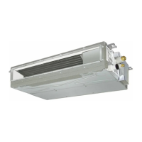
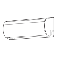
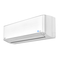
Lists detailed specifications for RAS-M10SKV-E, RAS-M13SKV-E, RAS-M16SKV-E and SKCV-E series indoor units.
Covers safety precautions specific to R410A refrigerant handling, installation, and servicing.
Explains piping materials, processing, and flare/joint procedures for R410A systems.
Lists exclusive and general tools required for R410A refrigerant system installation.
Details the step-by-step procedure for recharging refrigerant into the system.
Covers materials for brazing, flux usage, and brazing methods to prevent oxidation.
Provides wiring diagrams for RAS-M10SKV-E, RAS-M13SKV-E, RAS-M10SKCV-E, RAS-M13SKCV-E.
Provides wiring diagrams for RAS-M16SKV-E and RAS-M16SKCV-E models.
Illustrates the control flow and components for the indoor unit and remote controller.
Provides an overview of the air conditioner's control system, roles of indoor/outdoor units.
Explains various operation modes like AUTO, DRY, ECO, QUIET, and timer functions.
Details how to set, cancel, and behavior during power failure for auto restart.
Describes the functions and operations of the wireless remote controller.
Explains intermittent operation control for indoor fans during heating thermo-off.
Shows diagrams for indoor and outdoor unit installation placement and mounting.
Lists optional installation parts, accessories, and tools included with the unit.
Covers indoor unit placement, drilling, electrical work, piping, and drainage setup.
Guides initial checks for power supply, voltage, and normal program operations.
Outlines methods for diagnosing troubles, including LED flashing and symptom checks.
Explains self-diagnosis codes indicated by indoor unit LEDs for troubleshooting.
Details how to use the remote controller in service mode for self-diagnosis and check codes.
Provides troubleshooting steps based on specific symptoms like wiring failures and unit operation issues.
Describes procedures for checking key components like P.C. boards and sensors.
Provides step-by-step instructions for replacing main parts of the indoor unit.
Lists and illustrates exploded views of indoor unit parts with their corresponding part numbers.
| Power Supply | 220-240V, 50Hz |
|---|---|
| Refrigerant | R32 |
| Energy Efficiency Ratio (EER) | 3.21 |
| Coefficient of Performance (COP) | 3.61 |
| Outdoor Unit Dimensions (W x H x D) | 780 x 550 x 290 mm |
| Indoor Unit Weight | 9 kg |
| Noise Level (Indoor Unit) | 42 dB(A) |
| Noise Level (Outdoor Unit) | 50 dB(A) |
| Type | Split System |