Do you have a question about the Toshiba RAS-M16YKV-E and is the answer not in the manual?
Detailed performance and characteristic data for various indoor and outdoor unit models.
Electrical specifications including power supply, current, and component ratings for outdoor units.
Essential safety precautions for handling R410A refrigerant during installation and servicing.
Guidelines for selecting and installing copper pipes and joints suitable for R410A refrigerant.
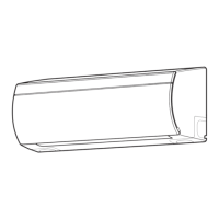
Exploded view and dimensions of the indoor unit components for assembly and identification.
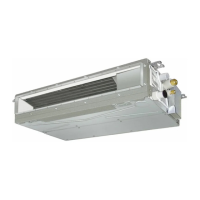
Exploded view and dimensions of the outdoor unit components, showing assembly and layout.
Detailed wiring diagram for the indoor unit, including component connections and color identification.
Comprehensive wiring diagram for the outdoor unit, illustrating P.C. board connections and component layout.
List of electrical parts used in the indoor unit, including part names, types, and specifications.
List of electrical components for the outdoor unit, detailing model names and ratings.
Operational data for cooling mode, showing conditions, combinations, and performance parameters.
Block diagram illustrating the indoor unit's control system, functions, and remote controller interface.
Block diagram of the outdoor unit's inverter assembly, showing control signals and component interactions.
Overview of the air conditioner's control system, including indoor and outdoor unit roles and communication.
Detailed explanation of operation circuits for cooling, heating, and fan-only modes, including control logic.
Explanation of the auto restart feature and how to set or cancel it for power outage recovery.
Identification of remote controller parts and indications, with explanations for cooling-only and heat pump models.
Critical safety warnings and precautions for installing the air conditioner, especially regarding electrical work and refrigerant.
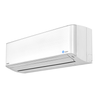
Step-by-step guide for installing the indoor unit, including accessory attachment and placement.
Detailed steps for installing refrigerant pipes and drain hoses, including bending and insulation requirements.
Guidelines for outdoor unit installation, including accessory parts and placement considerations.
Initial checks for power supply, voltage, and normal operation status to confirm basic functionality.
Interpreting indoor unit LED indications for self-diagnosis and identifying protective circuit operations.
Troubleshooting guide based on symptoms like power failure, fan issues, or wiring problems.
Procedures for checking key components like P.C. boards, sensors, and motors for defects.
Detailed instructions for replacing main parts of the indoor unit, including front panel, P.C. boards, and motors.
Steps for detaching and replacing components of the outdoor unit, such as panels, inverter assembly, and control boards.
Exploded view and parts list for the indoor unit (part 1), identifying components by location and part number.
Exploded view and parts list for the outdoor unit, showing component identification and part numbers.
Layout diagrams for P.C. boards in the RAS-4M27YAV-E, showing component placement and sensor connections.
| Type | Split System |
|---|---|
| Refrigerant | R32 |
| Energy Efficiency Class (Cooling) | A++ |
| Energy Efficiency Class (Heating) | A+ |
| Power Supply | 220-240 V, 50 Hz |
| Outdoor Unit Weight | 30 kg |
| Outdoor Unit Dimensions (W x H x D) | 780 x 550 x 290 mm |