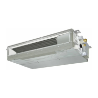
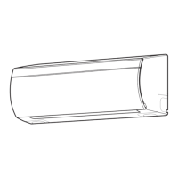
Do you have a question about the Toshiba RAS-M16NKV-E and is the answer not in the manual?
Details wiring for 10k and 13k indoor unit models.
Details wiring for the 16k indoor unit model.
Lists electrical parts specs for 10k and 13k indoor unit models.
Lists electrical parts specs for the 16k indoor unit model.
Outlines the control block diagram for the indoor unit's operations.
Describes the overall control structure and roles of indoor and outdoor units.
Explains capacity control, current release, power factor, and fan controls.
Covers operation circuit, fan-only, cooling, dry, and heating modes.
Details auto, hi power, comfort sleep, quiet, and ECONO operations.
Explains temporary operations, auto restart, and filter check functions.
Lists and describes the functions of each button on the remote control.
Explains the meaning of indicators and symbols shown on the remote control display.
Provides essential safety precautions for installing the air conditioner unit.
Lists required installation tools and illustrates the indoor unit installation process.
Covers installation place, electrical work, wiring, piping, and drainage procedures.
Explains how to fix the unit, set remote controls, and perform installation checks.
Verifies power, voltage, and interprets indoor unit LED blinking patterns for diagnosis.
Guides using remote control for diagnosis and provides servicing cautions.
Outlines methods for diagnosing troubles based on symptoms, including power and fan issues.
Provides specific troubleshooting steps for indoor fan issues on 16k models and fan motor rotation.
Details procedures for checking P.C. boards, main parts, and other indoor unit components.
Provides step-by-step instructions for replacing main parts within the indoor unit.
Shows an exploded view and parts list for the indoor unit's assembly.
Provides a detailed list of parts for the indoor unit with corresponding numbers.
| Brand | Toshiba |
|---|---|
| Model | RAS-M16NKV-E |
| Category | Air Conditioner |
| Language | English |


 Loading...