Do you have a question about the Toshiba RAS-M16UKCV-E3 and is the answer not in the manual?
Details the technical specifications for the air conditioner units.
Outlines performance specs when indoor units are combined with an outdoor unit.
Safety precautions for handling refrigerant R410A during installation and servicing.
Details on refrigerant piping materials, joints, and processing for R410A systems.
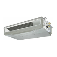
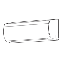
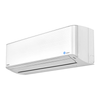
Provides detailed diagrams of the indoor unit's construction and dimensions.
Provides detailed diagrams of the outdoor unit's construction and dimensions.
Illustrates the wiring connections for the indoor unit.
Illustrates the wiring connections for the outdoor unit.
Lists the electrical components and their specifications for the indoor unit.
Lists the electrical components and their specifications for the outdoor unit.
Details operational data for the outdoor unit under various conditions.
Diagram showing the control flow and components of the indoor unit.
Diagram showing the control flow and components of the outdoor unit.
Overview of the air conditioner's control system and functions.
Explains how the air conditioner controls its capacity via compressor speed.
Describes the system to prevent freezing of the indoor heat exchanger.
Details the control mechanism for the outdoor fan motor.
Describes the operation procedures and logic for cooling mode.
Details the operation procedures and logic for dry mode.
Describes the operation procedures and logic for heating mode.
Explains the functions of temporary auto and cooling operations.
Details the auto restart feature and its setup/cancellation procedures.
Explains the functions and indications of the remote control.
Provides critical safety warnings and precautions for installation.
Steps for installing the indoor unit, including accessory and parts.
Instructions on how to connect the wiring for the indoor unit.
Procedures for securely fixing the indoor unit to the installation plate.
Guide on setting the remote controller selector switch for multi-unit systems.
Steps for checking and testing the unit after installation.
Guidelines for installing the outdoor unit, including placement and piping.
Details on connecting refrigerant pipes, including flaring and torque specifications.
Provides guidelines for installing the outdoor unit, considering clearances and wind.
Procedure for evacuating air from the refrigerant pipes using a vacuum pump.
Procedures for checking and testing the system after installation.
Procedure to check for miswiring or mispiping using LED indicators.
Initial checks for power supply and voltage confirmation.
Methods for initial diagnosis using indoor unit LEDs and remote control.
Interpreting indoor unit LED indications for self-diagnosis.
Using the remote control for self-diagnosis and retrieving check codes.
Troubleshooting based on observed symptoms and operational flowcharts.
Diagnosing outdoor unit issues using LED indicators.
Flowchart for diagnosing issues within the outdoor unit's inverter assembly.
Guides on checking main components like P.C. boards and motors.
Procedures for replacing main parts of the indoor unit.
Procedures for replacing main parts of the outdoor unit.
Exploded view and parts list for the indoor unit.
Exploded view and parts list for the outdoor unit.
Layout diagrams for P.C. boards used in the unit.
| Brand | Toshiba |
|---|---|
| Model | RAS-M16UKCV-E3 |
| Category | Air Conditioner |
| Language | English |