Do you have a question about the Toshiba RAS-M16UKCV-E and is the answer not in the manual?
Details unit models, cooling capacity, electrical characteristics, dimensions, piping, and refrigerant.
Safety precautions for R410A refrigerant handling during installation and servicing.
Guidelines for installing refrigerant piping, including materials and joints.
Lists required tools for installation and servicing, differentiating between R410A and conventional tools.
Step-by-step procedure for recharging refrigerant, including precautions and equipment.
Details materials and techniques for brazing refrigerant pipes to ensure secure connections.
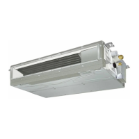
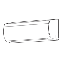
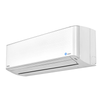
Exploded views and dimensions of the indoor unit components and installation.
Exploded views and dimensions of the outdoor unit components and installation.
Wiring diagram and color identification for the indoor unit.
Wiring diagram for the outdoor unit, detailing connections and components.
List of electrical parts and their specifications for the indoor unit models.
List of electrical parts and their specifications for the outdoor unit.
Schematic diagram illustrating the refrigerant flow and key components of the system.
Presents operation data based on temperature conditions and unit combinations.
Block diagram showing the control functions and signals within the indoor unit.
Block diagram of the outdoor unit's inverter assembly, detailing control signals and components.
Details operation modes, control logic, fan operation, and system performance parameters.
Explains operational circuits for fan-only, cooling, dry, and auto modes.
Covers temporary operation, auto restart function, and power failure handling.
Details remote control functions, buttons, and display indications.
Covers safety guidelines for installation and lists necessary tools, including R410A specific ones.
Details accessory parts and procedures for installing the indoor unit, including mounting, wiring, and drainage.
Covers outdoor unit accessories, installation place, piping, electrical work, and final checks.
Basic checks for power, voltage, and initial troubleshooting steps.
Diagnosing faults using indoor unit LEDs and remote control service mode.
Troubleshooting outdoor unit faults via LEDs and symptom-based analysis.
Procedures for replacing front panel, electrical parts, microcomputer, and louvers of the indoor unit.
Steps for replacing outdoor unit components: cabinets, inverter, boards, motors, compressor, and reactor.
Detailed steps for replacing temperature sensors, including preparation and soldering.
Exploded view and parts list for the indoor unit components.
Exploded view and parts list for the outdoor unit components.
Diagrams showing the layout of components on the main P.C. boards.
| Heating Capacity | 5.0 kW |
|---|---|
| Energy Efficiency Ratio (EER) | 3.21 |
| Refrigerant | R32 |
| Outdoor Unit Dimensions (W x H x D) | 780 x 550 x 290 mm |
| Weight (Outdoor Unit) | 34 kg |
| Noise Level (Outdoor) | 50 dB(A) |
| Power Supply | 220-240V, 50Hz |
| Coefficient of Performance (COP) | 3.61 |
| Type | Air Conditioner |
| Noise Level (Indoor) | 21 dB |