Design Conditions for customers DX Coil
• The DX-Coil MUST be operated within the following limits to ensure reliability:-
o Cooling mode DX coil “air on” temp: Min: 15°CWB (18°CDB) ~ Max: 24°CWB (32°CDB)
o Heating mode DX coil “air on” temp: Min: 15°CDB ~ Max: 28°CDB
• When used for Ventilation, the DX-Coil MUST be combined with other equipment such as heat recovery exchanger or heaters /
coolers to ensure that the CA limits are not exceeded:-
Coil Air (After Heat Recovery Exchanger)
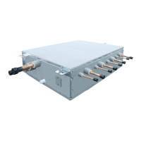
Recommended No. of Ref. Circuit by DX-Coil U-Pipe Dia. and DX Coil Size (HP)
8.00
9.52
12.70
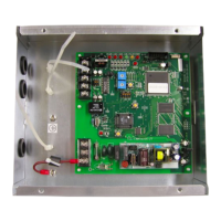
IP65
If the wiring is properly carried out by a specialist according to the local regulations, the device fulfills the protection class
IP65.
Automatic Mode
Please be aware that frequent mode changes could occur when using Automatic mode
 Loading...