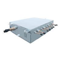
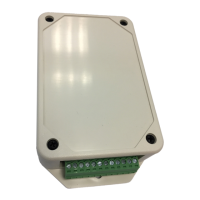
LC DX INTERFACE
The DX controller must not be installed outside. To avoid damage, when making holes for cables glands,
please first remove the Gland Plate from the LC DX Interface. To maintain waterproof integrity IP65 glands
must be used through the gland plate.
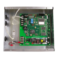
Note: In areas where
there is a risk of dew
condensation
insulation (locally
sourced) should be
fitted to the DX
controller enclosure
PIPING SCHEMATIC
Notes:
1) To ensure reliable operation, all Sensor Holders must be fitted by brazing.
2) The TC Sensor Holder must be brazed to return bend 2/3
rd
’s through pass on the DX Coil’s lowest circuit.
3) For brazing, be sure to use nitrogen gas to avoid oxidation of pipe inner surface.
Weight: 10kg
Dimensions Mounting Holes
Sensor Holder
(Brazing)
Sensor Holder
(Brazing)
Lowest Circuit
(2/3
rd
’s through Pass)
(TA)
 Loading...