Do you have a question about the Toshiba RAV-SM1103AT-E1 and is the answer not in the manual?
| Brand | Toshiba |
|---|---|
| Model | RAV-SM1103AT-E1 |
| Category | Air Conditioner |
| Language | English |
Describes qualifications and knowledge required for installers and service persons.
Specifies protective gear to be worn for different types of work.
Defines danger, warning, caution indications and illustrated safety marks.
Details warning labels on the main unit and their descriptions.
Critical safety warnings including electrical shock and discharge procedures.
General warnings for installation, servicing, and electrical work.
Covers electrical safety, grounding, parts usage, and environmental awareness.
Precautions regarding refrigerant R410A, assembly, insulation, ventilation, and leaks.
Procedures for checks after repair, operating with valves closed, and installation safety.
Guidelines for relocating the air conditioner unit.
Instructions for proper disposal of the product.
Highlights safety concerns related to the new R410A refrigerant.
Specific precautions for installation and servicing with R410A.
Details requirements for copper pipes and joints used with R410A.
Lists tools exclusively for R410A and their interchangeability.
Lists conventional tools that can be used with R410A.
Technical specifications for the outdoor unit, including dimensions, weight, and performance.
Graphs showing current draw relative to compressor speed for cooling and heating.
Graphs illustrating capacity variation based on outdoor temperature.
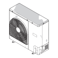
Detailed external views with dimensions, ports, and service space requirements.
Diagram showing the path of refrigerant and the location of major components.
Wiring diagram for the outdoor control P.C. board with component identification.
Detailed table of electrical parts, their types, and specifications.
Safety precautions for handling R410A during installation and servicing.
Guidelines for installing refrigerant piping, including materials and joints.
Procedures and precautions for connecting flare nuts and seal surfaces.
Reference values for tightening torque of flare connections for R410A.
Step-by-step guide for recharging refrigerant, including equipment and procedures.
Details on materials and flux used for brazing pipes.
Technique for brazing while preventing oxidation using nitrogen gas.
Basic conditions and restricted cases for reusing existing refrigerant pipes.
Methods for curing pipes when units are removed for extended periods.
Procedure for checking existing pipes before reuse, including flare machining.
Guidelines and cautions for reusing existing pipes, including wall thickness requirements.
Overview of the primary circuit board (MCC-1630) and its connections.
Describes the control logic for the PMV based on temperature differences.
How discharge temperature affects operation frequency and compressor stops.
Details how the outdoor fan speed is controlled based on sensors and frequency.
Explains heating fan speed control based on TE, TO sensors and frequency.
Function for heating the compressor to prevent refrigerant stagnation.
Protects the compressor from short cycling after startup.
Restrains high pressure by controlling operation frequency.
Operation sequence and conditions for defrosting the outdoor unit.
Compressor stop mechanism related to case temperature.
Initial checks and troubleshooting procedures for wired remote controllers.
Initial checks and troubleshooting procedures for wireless remote controllers.
Method for judging errors using lamp indications and check codes.
Identifies issues that do not generate specific check codes.
Procedure to display sensor values and operating data via the remote controller.
Comprehensive list of outdoor unit error codes, their causes, and detection methods.
Table detailing error modes detected by the indoor unit.
Table detailing error modes detected by the outdoor unit.
Lists error codes related to communication between controllers and units.
Explains how LEDs on the outdoor PC board indicate errors.
Guides for diagnosing errors using LED displays and service switches.
Step-by-step troubleshooting for communication errors.
Flowcharts for diagnosing errors related to discharge and heat exchanger sensors.
Flowcharts for diagnosing errors related to outside air, suction, and miswired sensors.
Flowcharts for EEPROM, compressor breakdown, and lock errors.
Flowcharts for current circuit, model setting, and discharge temp errors.
Flowchart for diagnosing high pressure switch and protective operation errors.
Flowcharts for power supply, heat sink overheat, and gas leak detection.
Flowchart for diagnosing 4-way valve reversal errors.
Flowchart for diagnosing high pressure protective operation.
Flowchart and method for diagnosing outdoor fan system errors.
Flowcharts for short-circuit compressor drive and position detection errors.
Tables and graphs showing resistance values for various temperature sensors.
Procedures for measuring resistance of compressor, fan motor, and 4-way valve coil.
Procedure to retrieve past error logs from the remote controller.
Explanation of controlling multiple indoor units as a group.
Describes the sequence for automatic address setup when units are powered on.
Method for performing refrigerant recovery operation using the outdoor unit.
How to configure settings like existing pipes and power save using service switches.
Procedure to change the unit's setting to cooling-only mode.
How to switch the displayed information on the outdoor unit's LEDs.
Explains how to view current and historical errors via LED indicators.
Shows how to view sensor readings, current, and compressor frequency.
Procedures for special operations like refrigerant recovery and fan testing.
Details on controls enabled by the application control kit.
Step-by-step guide for setting addresses for indoor and outdoor units.
Explains system configurations (single, twin, group) and terminology.
Illustrates automatic address setup for various system configurations.
Shows wiring connections for remote controllers in single and twin systems.
Instructions for manually setting addresses using the remote controller.
Procedure to check the recognized indoor unit addresses.
How to check unit positions in group control and maintenance checks.
Steps for removing and installing the service P.C. board, including jumper wire settings.
Overview of the steps involved in exchanging the compressor.
General steps for disassembling and assembling unit parts, with safety cautions.
Procedure for detaching and attaching the discharge port cabinet.
Steps for removing and installing the inverter assembly.
Procedure for removing and installing the outdoor unit control P.C. board.
Steps for removing and installing the fan motor.
Detailed steps for removing the compressor.
Procedures for removing the PMV coil and reactor.
Steps for removing and installing the fan guard.
Diagram showing the assembly of outdoor unit parts with reference numbers.
Table listing part numbers, descriptions, and quantities for the outdoor unit.
List of parts specific to the inverter assembly.