Do you have a question about the Toshiba RAV-SP564ATP-A and is the answer not in the manual?
Defines the qualifications and knowledge required for installation and service personnel.
Details the protective gear necessary for various work activities to ensure safety.
Explains the warning labels and their meanings on the air conditioner unit.
Outlines general safety precautions, including handling of refrigerants and electrical safety.
Discusses warnings related to refrigerant leakage and concentration limits in rooms.
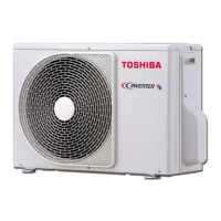
Technical specifications for the outdoor unit, including dimensions and electrical data.
Graphs showing the relationship between compressor speed and current for cooling and heating.
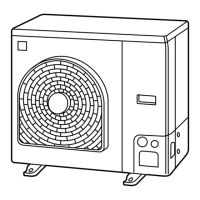
External views and dimensions of the RAV-SP56*ATP* outdoor unit.
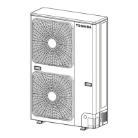
External views and dimensions of the RAV-SP80*ATP* outdoor unit.
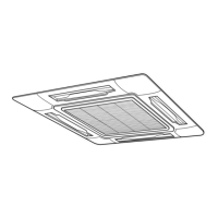
Refrigerating cycle diagram for the indoor unit, including distributor and sensors.
Refrigerating cycle diagram for the outdoor unit, including compressor and heat exchanger.
Wiring diagram for the RAV-SP56*ATP* outdoor unit, showing electrical connections.
Wiring diagram for the RAV-SP80*ATP* outdoor unit, showing electrical connections.
Crucial safety precautions for handling R410A refrigerant during installation and servicing.
Guidelines and requirements for installing refrigerant piping, including material specifications.
List of required tools for R410A installation and servicing.
Step-by-step procedure for recharging refrigerant, including necessary precautions.
Instructions and materials for brazing refrigerant pipes, emphasizing safety and proper technique.
Conditions and restrictions for reusing existing R22 or R407C piping with R410A systems.
Restrictions and procedures for replenishing refrigerant to ensure reliability and prevent hazards.
Explanation of various control functions and operations within the outdoor unit.
Identification and description of components on the outdoor unit's print circuit board.
An overview of common troubleshooting steps and required tools.
Detailed troubleshooting procedures based on error codes and symptoms for various units.
A table showing main outdoor unit parts and their checking procedures using a tester.
Procedure for controlling refrigerant recovery (pump down) using switches on the outdoor unit.
Explanation of various settings configurable via DIP switches and jumper lines on the outdoor unit.
Details on using LED displays and switches for service support, diagnostics, and status checks.
Step-by-step instructions for detaching and attaching parts of the RAV-SP56*ATP* outdoor unit.
Step-by-step instructions for detaching and attaching parts of the RAV-SP80*ATP* outdoor unit.
Exploded view diagram and parts list for the RAV-SP564ATP-A model.
Exploded view diagram and parts list for the RAV-SP804ATP-A model.
| Brand | Toshiba |
|---|---|
| Model | RAV-SP564ATP-A |
| Category | Air Conditioner |
| Language | English |