Do you have a question about the Toshiba RBM-PMV0361UP-E and is the answer not in the manual?
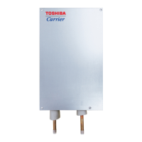
This document outlines the installation and maintenance procedures for the Toshiba PMV Kit (RBM-PMV0361UP-E and RBM-PMV0901UP-E), designed to enhance the performance and reduce noise levels of Toshiba air conditioning systems, particularly in quiet environments. The PMV Kit works with HFC refrigerants (R32 or R410A), which are ozone-friendly.
The PMV Kit is primarily designed to mitigate refrigerant noise originating from the Pulse Motor Valve (PMV) within multi-indoor unit air conditioning systems. In scenarios where indoor units operate in very quiet rooms or where users are particularly sensitive to noise, the PMV Kit redirects the source of refrigerant noise away from the living space. By shifting the control function of refrigerant flow to the PMV Kit, the PMV in the indoor unit is no longer actively used for this purpose. This allows the refrigerant noise, which typically manifests as sounds like "gobo... gobo.... glug glug...." or "Shuru shuru...", to emanate from the PMV Kit, which is installed in an isolated area such as above a ceiling board or in a passage way, thereby significantly reducing the noise perceived within the indoor living space.
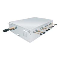
The kit includes a connection cable, heat insulating pipes, various binding bands (L, M, S), and an attached joint and seal pipe for specific refrigerant pipe connections. It also comes with clamp filters, which are crucial for ensuring electromagnetic compatibility (EMC) standards are met and preventing malfunctions of electronic devices.
Installation and Placement: The PMV Kit should be installed in a location that can horizontally support its weight and allow for adequate service space for maintenance or checks. It is recommended to install the unit in a soundproofed area, such as above a ceiling, using soundproof materials like drywalls. Crucially, the unit should not be installed outdoors. A check opening (at least 450 x 450 mm) must be provided if the unit is installed within a ceiling. A minimum clearance of 20 mm is required between the top panel of the unit and the ceiling. The connection pipe length to the indoor unit should be between 2 m and 10 m, with 5 m or longer being more effective for noise reduction.
Refrigerant Piping: The PMV Kit is compatible with R32 or R410A refrigerants, which require specific installation practices due to their high pressure and sensitivity to impurities. Copper pipes with a thickness of 0.8 mm or more (for Dia. 6.4, 9.5, 12.7 mm) must be used. Special flare nuts and flaring tools designed for R32 or R410A are necessary, as their flaring sizes differ from those used with R22 refrigerant. When connecting Dia. 9.5 refrigerant pipes, a seal pipe must be inserted between the PMV main unit and the joint to prevent leakage.
Noise Reduction: To maximize noise reduction, the PMV Kit should be installed in isolated spaces, away from areas with low background noise such as bedrooms, hospital rooms, or hotel rooms. It should also be avoided in rooms without ceiling boards or with opening parts on the ceiling where the PMV Kit is not isolated from the living space. To prevent sound and vibration propagation, cushion material should be wrapped around the liquid pipes of the PMV Kit, and the unit should be secured with hanging bolts at intervals of 1 m or less. If mounted on a wall, cushion material must be placed between the PMV Kit and the wall.
Electrical Work: Electrical work must adhere to local regulations and the Installation Manual, using specified wires and an exclusive power circuit. Wires must be securely connected and fixed to prevent external tension from affecting terminals, which could lead to fire or electric shock. The wiring should not come into contact with high-temperature parts of the pipe. Clamp filters, supplied as accessories, are essential for EMC compliance and must be installed on both the PMV Kit side and the indoor unit side at specified positions to prevent electronic device malfunctions.
Safety Precautions: Prior to any maintenance, the main power supply switch or breaker must be turned off to prevent electric shock. Maintenance should only be performed by authorized dealers or qualified installation professionals. The Installation Manual, along with the Owner's Manual, should be kept for reference.
Refrigerant Handling: When working with R32 or R410A refrigerants, extreme care must be taken to prevent moisture, dirt, existing refrigerant, or refrigerating machine oil from mixing into the refrigeration cycle, as this can lead to abnormally high gas pressure and pipe bursts. A special tool for R32 or R410A refrigerant is required for installation and maintenance. New and clean piping materials should be used.
Leak Detection: After installation or any work involving the refrigerant system, a thorough leak check must be performed. Electronic leak detectors suitable for HFC refrigerants (R32 or R410A, R134a, etc.) should be used. Halide torches or any other detectors using a naked flame are prohibited for flammable refrigerants. Leak detection equipment must be calibrated to the refrigerant employed and set at a percentage of the LFL (Lower Flammable Limit) of the refrigerant (25% maximum). If a leak is suspected, all naked flames must be removed.
Airtight Test and Air Purge: Before turning on the power, an airtight test and vacuuming must be completed. The vacuum pump outlet should not be near any ignition sources, and adequate ventilation must be available. Oxygen-free nitrogen (OFN) should be purged through the system before and during brazing processes to ensure safety.
Heat Insulation: Heat insulating pipes must be securely applied to the liquid and gas sides of the PMV Kit's pipe connecting sections, extending to the root without exposing the pipe, to prevent dewing and water leakage. For the gas side, insulation with a heat-resisting temperature of 120°C or more is required. Depending on the environment, extra heat insulation may be needed on the liquid pipe between the PMV Kit and the indoor unit to prevent condensation.
Decommissioning and Recovery: When decommissioning or removing refrigerant, all refrigerants must be recovered safely into appropriate recovery cylinders. The system should be labeled to indicate it has been decommissioned and emptied of refrigerant. Compressors or compressor oils must be evacuated to an acceptable level to ensure no flammable refrigerant remains within the lubricant before returning them to suppliers. Only electric heating should be used to accelerate this process.
| Power Supply (V/Hz/Ph) | 208-230/60/1 |
|---|---|
| Cooling Capacity (BTU) | 36000 |
| Heating Capacity (BTU) | 36000 |
| Refrigerant | R410A |
| Power Supply | 208-230V, 60Hz, 1Ph |