EasyManua.ls Logo

Toshiba RT-S652 - SW Band Receiver Alignment; FM Receiver IF and RF Alignment

Toshiba RT-S652
20 pages
Print Icon
To Next Page IconTo Next Page
To Previous Page IconTo Previous Page
Loading...
|
RT—S652
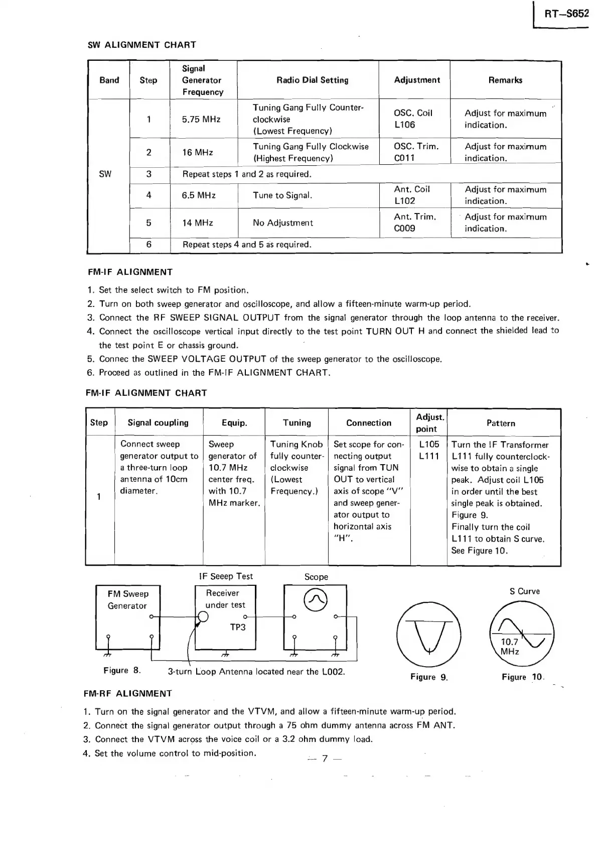
SW
ALIGNMENT
CHART
Signal
Generator
Radio
Dial
Setting
Adjustment
Remarks
Frequency
Tuning
Gang
Fully
Counter-
5.75
MHz
clockwise
(Lowest
Frequency)
OSC.
Coil
Adjust
for
maximum
‘
L106
indication.
Tuning
Gang
Fully
Clockwise
OSC.
Trim.
Adjust
for
maximum
Toe
(Highest
Frequency)
C011
indication.
Repeat
steps
1
and
2
as
required.
Ant.
Coil
Adjust
for
maximum
L102
indication.
Ant.
Trim,
’
Adjust
for
maximum
Ccoo9
indication.
6.5
MHz
Tune
to
Signal.
14
MHz
No
Adjustment
Repeat
steps
4
and
5
as
required.
FM-IF
ALIGNMENT
.
Set
the
select
switch
to
FM
position.
.
Turn
on
both
sweep
generator
and
oscilloscope,
and
allow
a
fifteen-minute
warm-up
period.
.
Connect
the
RF
SWEEP
SIGNAL
OUTPUT
from
the
signal
generator
through
the
loop
antenna
to
the
receiver.
.
Connect
the
oscilloscope
vertical
input
directly
to
the
test
point
TURN
OUT
H
and
connect
the
shielded
lead
to
the
test
point
E
or
chassis
ground.
:
5.
Connec
the
SWEEP
VOLTAGE
OUTPUT
of
the
sweep
generator
to
the
oscilloscope.
6.
Proceed
as
outlined
in
the
FM-IF
ALIGNMENT
CHART.
PWN
=
FM-IF
ALIGNMENT
CHART
Signal
coupling
Equip.
Tuning
Connection
Pattern
Connect
sweep
Sweep
Tuning
Knob
|
Set
scope
for
con-
Turn
the
!F
Transformer
generator
output
to
|
generator
of
|
fully
counter-
|
necting
output
L111
fully
counterclock-
a
three-turn
loop
10.7
MHz
clockwise
signal
from
TUN
wise
to
obtain
a
single
antenna
of
10cm
center
freq.
(Lowest
OUT
to
vertical
peak.
Adjust
coil
L105
diameter.
with
10.7
Frequency.)
axis
of
scope
“V"’
in
order
until
the
best
MHz
marker.
and
sweep
gener-
single
peak
is
obtained.
ator
output
to
Figure
9.
horizontal
axis
Finally
turn
the
coil
“H",
L111
to
obtain
S
curve.
See
Figure
10.
IF
Seeep
Test
FM
Sweep
Receiver
S
Curve
Generator
under
test
ae
aS
Figure
8.
-
F
igure
3-turn
Loop
Antenna
located
near
the
LOO2.
Figure
9.
Figure
10.
FM-RF
ALIGNMENT
1.
Turn
on
the
signal
generator
and
the
VTVM,
and
allow
a
fifteen-minute
warm-up
period.
2.
Connect
the
signal
generator
output
through
a
75
ohm
dummy
antenna
across
FM
ANT.
3.
Connect
the
VTVM
across
the
voice
coil
or
a
3.2
ohm
dummy
load.
4.
Set
the
volume
control
to
mid-position.
7