SW1
CENTRAL
LAST-PUSH
SW1
Accessories
• Accessory No.1 connecting cables is already connected.
No.
2 M4 tapping screw
1
Cable (For CN61 connector, with 6P connectors, L=1.5m)
Name
Q'
ty
1 pc.
4 pcs.
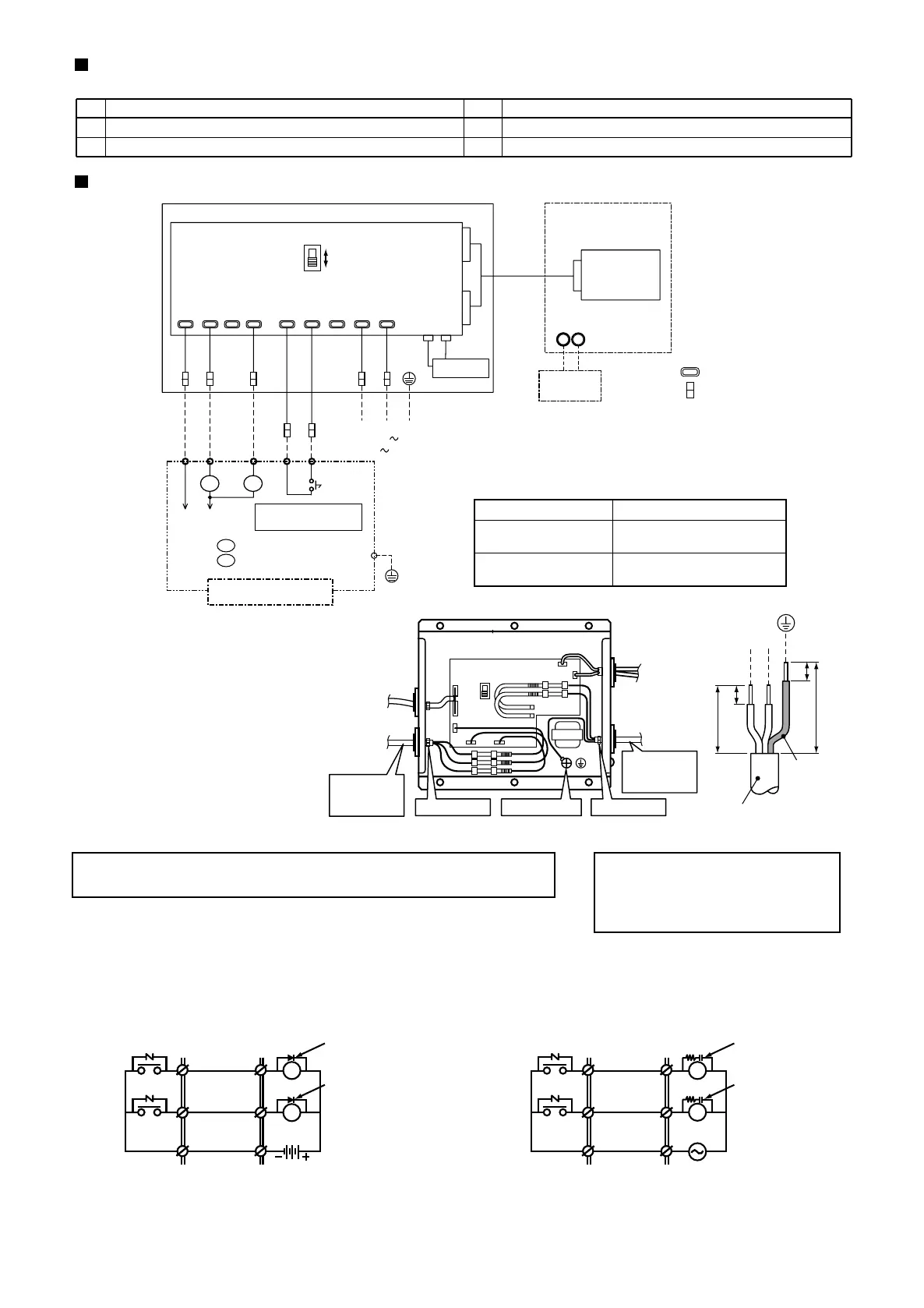
Wiring diagram
CN13
CN06
P.C. board for
Indoor unit
CN61
Electric parts box
of indoor unit
Wired remote
controller
AB
Remote location for ON/OFF control box
P.C. board
Power input
LN
ON
COM
ALARM
COM
OPERATION
Transformer
TP5TP4TP2TP1TP3TP9
TP10
TP8TP7
Blue
Gray
Pink
Red
Black
Yellow
White
Power supply cable
ON/OFF command
signal cable
Indication signal cable
Up to 80m : 3-core, 0.75mm
2
Up to 500m : 2-core, 0.75mm
2
Up to 200m : 3-core, 0.75mm
2
Up to 400m : 3-core, 1.5mm
2
Non-voltage
ON/OFF continuous signal
Power supply
MAX. 240V 0.5A
L1 ON operation lamp
L2 Alarm indication lamp
Central panel
(Required at the site)
: Tab terminal
: Butt terminal
When using the air conditioner with central priority, remove the cover of interface adapter,
and select "CENTRAL" side of the select switch (SW 1) at near the center of P.C. board.
(Relays are used for central indication in order to prevent
malfunction by surge absorber.)
• Selecting of Central priority/Last-push priority
• Wiring method
The select switch has been previously set to LAST-PUSH side on shipment
from the factory.
• Notes on connecting relays
a. To drive induction load with DC power
(CAUTION)
Be sure to turn off the power supply of
interface adapter before selecting one
side on the select switch.
(Note)
Mount surge absorbers to both ends of the relay coil.
Use a surge absorber of which voltage tightness is 350V AC/500V
DC or more.
(Note)
Mount diodes to the both ends of the relay coil.
Select a diode of which back voltage tightness is 10 times or more
of the use voltage, and forward current is more than the load
current.
Diode
Diode
Central sideInterface side
ALARM
OPERATION
COM
Central sideInterface side
ALARM
OPERATION
COM
Surge absorber
Surge absorber
RY
RY
• Cable specifications (Local supply)
Name
Connected to connector CN61 on P.C. board of indoor unit
Remarks
For installation of this control box
L2L1
b. To drive induction load with AC power
***
***
***
In conformity with design 60245 IEC 57
(1) Power supply cable, earth, and indication signal
cable must be connected in this control box.
Detach the case cover of the control box, and
connect the cables with the terminal according
to the purpose.
(2) Be sure to fix the cable with the cable clamp.
(local supply)
Indication
signal cable
(local supply)
Power supply
cable
Cable clamp Earth terminal Cable clamp
Earth
terminal
Power supply
220-240V , 50Hz
220V , 60Hz
Power supply cable
Earth line
10
10
50
180
LN
(Unit mm)
RY
RY
*
**
*
For connecting, be sure to use the connected cable.
**
Supplementary insulation must be added to user touchable part of
switches.
Cables other than cables connected should be required at the site.
Be sure to use the mounting hole to fix the box.

 Loading...


