Do you have a question about the Toshiba TCB-IFDA1GUL and is the answer not in the manual?
Guidelines for choosing an appropriate installation site to ensure safety and performance.
Procedures and considerations for physically installing the unit securely and safely.
Safe and correct methods for installing refrigerant piping, including leak checks.
Guidelines for safe and compliant electrical wiring practices for the unit.
Steps to perform a test run to verify the unit's functionality after installation.
Information to be provided to the end-user regarding operation and maintenance.
Procedures and safety precautions for relocating the air conditioner unit.
A diagram illustrating the connection of the Dx-Interface with other system components.
Table detailing connectivity of 3rd party DX-Coils by capacity and system type.
Specifications and configuration for normal coil types, including large coil sizes.
Specifications and configuration for split face and interlaced coil types.
Key notes and features regarding AHU/DX-Coil selection and performance.
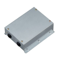
List of parts included with the TCB-IFDA1GUL Dx-Controller.
List of parts included with the various VRF Dx-PMV kits.
Instructions for mounting the Dx-Controller unit in its designated location.
Limits for refrigerant piping length and height difference for system design.
Specifications for selecting and connecting refrigerant pipes for the Dx-Coil.
Schematic and preparation guidelines for the DX Coil and its piping.
Important cautions and notes to follow during the brazing process for the Dx-PMV kit.
Instructions for securing and installing the TA Sensor correctly.
Specifications for power supply and communication wiring for the system.
Details on the power supply requirements and connections for the Dx-Controller.
Specifications for the VRF communication line between units.
Wiring specifications for connecting the remote controller.
Wiring details for the PMV (Pulse Motor Valve) control signals.
Procedure for setting up VRF addresses for system communication.
Diagram showing the electrical connection terminals on the Dx-Controller.
Description of power supply and communication line terminals and their functions.
Explanation of digital input and output terminals for system control.
Details on connecting temperature sensors and PMV to the controller.
Wiring configurations for PMV based on normal or split/interlaced coil types.
Settings and configuration options for the Dx-Controller with external controls.
Step-by-step guide on how to change settings for applicable controls.
A summary table of standard inputs and outputs for the system.
Configuration details for the main indoor PCB and its output functions.
Essential preparation steps before commencing the test run procedure.
Procedures for executing the test run to confirm system operation and identify issues.
Troubleshooting common issues related to the Dx-Controller.
Troubleshooting common issues when using the wired remote control.
A list and explanation of common error check codes for the system.
A detailed wiring diagram for the Dx-Controller RA control type.
Information about available wired remote controller options.
Details on central control and BMS interface compatibility.
The Toshiba Carrier Dx-Interface: Dx-Controller (RA control type), model TCB-IFDA1GUL, is an installation manual for a device designed to connect a third-party DX-Coil to a Toshiba Carrier VRF system (SMMS-e, SHRM-e). This controller supports DX-Coils up to 16 tons and functions as a VRF indoor unit. It is compatible with HFC R410A refrigerant, a new type adopted to prevent ozone layer destruction. The manual emphasizes that this appliance is for commercial use only and should not be accessible to the general public. Installation and maintenance must be performed by qualified personnel to prevent electric shock, fire, or other hazards.
The Dx-Controller (RA control type) facilitates the integration of third-party DX-Coils with Toshiba Carrier VRF systems. It manages the operation of the DX-Coil, allowing it to function as an indoor unit within the VRF network. The system requires an appropriately sized Dx-PMV kit, which must be brazed to the DX-Coil. The controller also supports larger DX-Coil applications by using two Dx-PMV kits with a single Dx-Controller in one DX-Coil, or interlaced/split-faced DX-Coils with multiple Dx-Controllers and Dx-PMV kits. The main PCB is common for both 0-10V type (TCB-IFDA1GUL) and analogue input type (TCB-IFDD1GUL), with the RA control type being the default configuration for this model.
| Brand | Toshiba |
|---|---|
| Model | TCB-IFDA1GUL |
| Category | Controller |
| Language | English |
