TCB-IFDA1GUL RA Control Type Wiring Diagram Rev3
3. Please refer to the installation manual for wiring instructions.
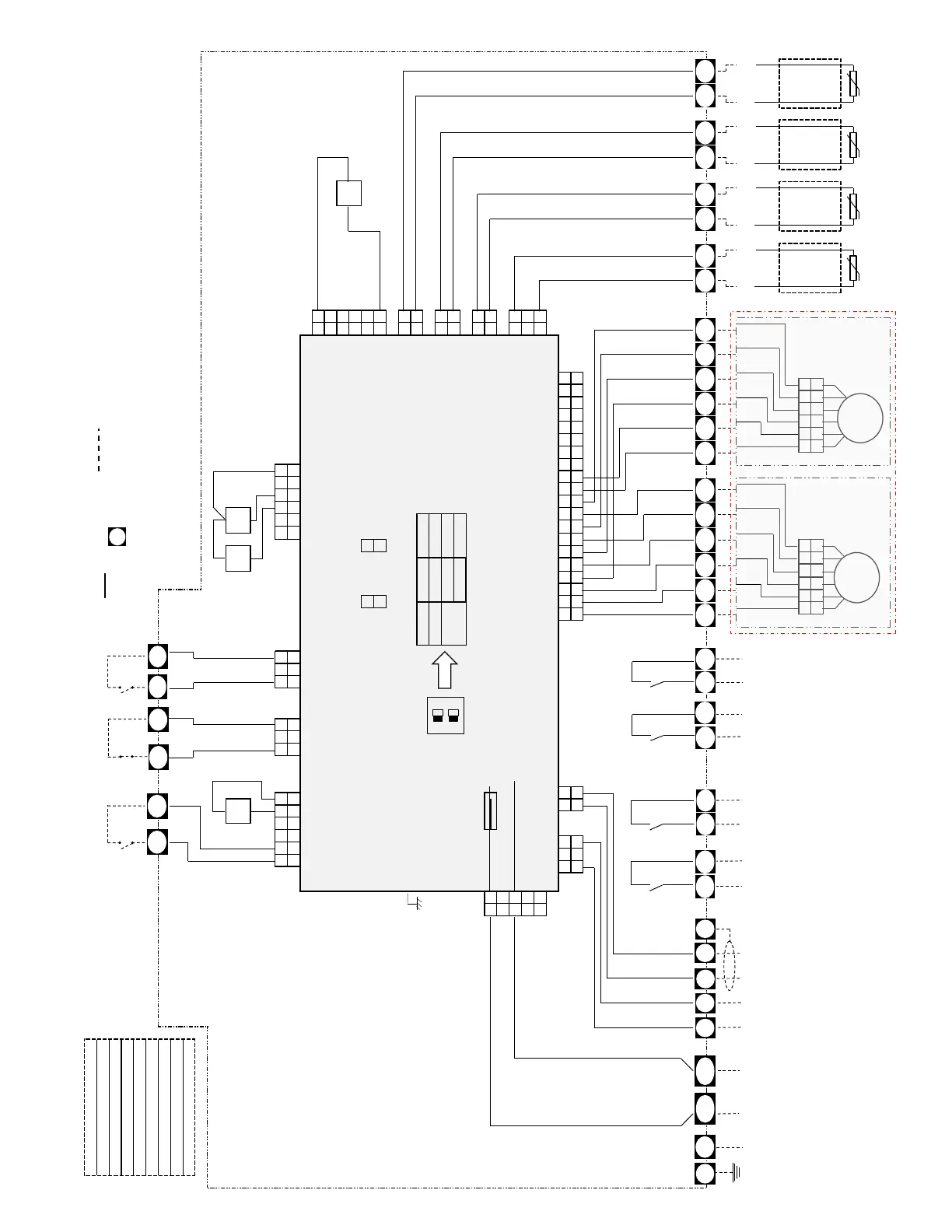
DX-Controller (RA control type) Wiring Diagram : TCB-IFDA1GUL
1. The dashed lines indicate wiring on site.
2. indicate terminal blocks and the numbers within them are the terminal numbers
External
ON/OFF input
Rating 12VDC
Safety contact
(Factory set : Closed)
Rating 12VDC
Fan Error Input
(Normally Open)
Rating 12VDC
4. The DX-Interface can be configured as a VRF system.
5. At shipment C5 and C6 are short-circuited. Remove it when you use the terminal.
(Classification of control against electric shock : CLASS I )
Power supply
208/230VAC
60Hz 1Ph
Thermo on
(NC)
Digital
Output
12VDC
Fan Motor
Active
Digital
Output
250VAC 6A
Alarm
Active
Digital
Output
250VAC 6A
Secondary
Heating
Output
12VDC
[NOTE 1] Low-Voltage Wiring : CLASS 2
ATTENTION: LE CÂBLAGE CONNECTÉ DANS CETTE BOÎTE DOIT ÊTRE ÉVALUÉ AU MOINS 300V.
[NOTE 2] Use Copper Conductors Only
CAUTION : WIRING CONNECTED IN THIS BOX MUST BE RATED AT LEAST 300V.
 Loading...


