19
Device Type / Capacity DN Code setting (Requires wired Remote Controller)
•Follow the basic operation Procedure (1 → 2 → 3 → 4 ) outlined above.
•The interface uses a new Device Type DN Code 10_55. This is set at the factory.
•The installer must set Capacity Code (DN Code 11). As default this is configured
as a 8ton model at the factory (DN 10_23). See table on next page.
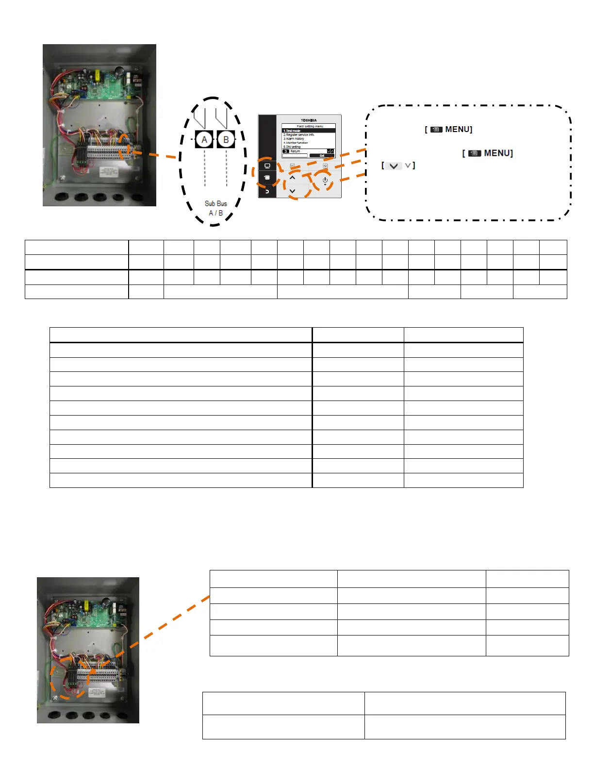
■Summary of Inputs and Outputs (Standard)
Sub-Bus (AB) : Remote controller wiring
Safety contact input (P10)
Fan Operation (Contact Rating: 250VAC 6A)
Alarm output (Contact Rating: 250VAC 6A)
Thermo ON (NC) output (Contact Rating : 250VAC 6A)
Secondary Heating Output / Cooling output
■Main Indoor PCB (MCC-1570): CN60/CN61/CN82 Configuration
•Digital output functions are available from the CN60/CN61/CN82 connector on the main indoor PCB (MCC-1570)
inside the DX-controller.
•For ease of installation connection to the CN60/CN61/CN82 outputs are made on the relays included in the DX interface.
As the factory setting, “CN82 Pin No.4” function is cooling output function.
Secondary heating function becomes effective to set up DN code [DC]
setting data [0001 to 0010].
Factory setting :
DN code [DC :0000]
Secondary heating :
DN code [DC : 0001 to 0010]
CN82, Pin No.4
➡Cooling output function
CN82, Pin No.4
➡Secondary heating output function
Cooling output /
Secondary heating output
<How to enter the DN setting>
1.Push the button to display
the menu screen.
2.Push and hold the and
button at the same time for more
than 4 seconds to display the “Field setting
menu” .
3. Select “7. DN setting” on the “Field setting
menu”, then push the [F2] button to set.
 Loading...


