EasyManua.ls Logo

Toshiba TCB-IFDMX01UP-E User Manual

Toshiba TCB-IFDMX01UP-E
58 pages
To Next Page IconTo Next Page
Page #1 background imageLoading...
Page #1 background image
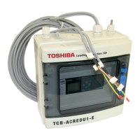
VRF DX COIL INTERFACE
MODEL NAME
Dx-coil controller
TCB-IFDMX01UP-E
(Terminal block without relay)
TCB-IFDMR01UP-E
(Terminal block with relay)
Dx-valve kit
RBM-A101UPVA-E
RBM-A201UPVA-E
Design Guideline
DG003-03

Other manuals for Toshiba TCB-IFDMX01UP-E

Questions and Answers:

Toshiba TCB-IFDMX01UP-E Specifications

General IconGeneral
BrandToshiba
ModelTCB-IFDMX01UP-E
CategoryAir Conditioner
LanguageEnglish

Summary

Application Types and Settings

TA Type Application

Explains TA type for room temperature conditioning.

DDC Type Application

Explains DDC type for discharge air temperature control.

TF Type Application

Explains TF type for ventilation control.

System Compatibility Overview

Outdoor Unit Compatibility

Compatibility of outdoor units with TA, DDC, TF types.

Operating Conditions

Coil on Air Temperature Ranges

Specifies required "Coil on Air" temperatures for different modes.

Pipe Sizing and Layout

Pipe Diameter Specifications

Pipe diameters based on outdoor unit capacity.

Valve Kit Piping Configurations

Diagrams for 1, 2, and 3 set valve kit configurations.

Pipe Length and Height Considerations

Piping Length and Height Limits

Max pipe length and height difference for TA/DDC/TF types.

Product Configuration, Specs & I/O Details

8HP~40HP Configurations

Component combinations for 8-40 HP models.

42HP~120HP Configurations

Component combinations for 42-120 HP models.

Dx-coil Controller Specifications

Major specs for Dx-coil controllers.

Dx-valve Kit Specifications

Major specs for Dx-valve kits.

Analog Input Functions

Details on analog inputs Al1 and Al2.

Analog Input Functions (Al3, Al4)

Details on analog inputs Al3 and Al4.

Digital Input Functions

Specifications for digital inputs DI1-DI6.

Digital Output Functions

Specifications for digital outputs DO1-DO6.

Digital Output Functions (DO7-DOE)

Specifications for digital outputs DO7-DOE.

Analog Output Functions

Details on analog outputs AO1 and AO2.

AHU / DX COIL Design Guidelines

Equipment Selection Procedure

Step-by-step flowchart for selecting equipment.

Outdoor Unit Capacity Correction Charts

Charts for correcting capacity based on temperature.

Additional Refrigerant Calculation

Guidelines for calculating additional refrigerant charge.

DX COIL Design Guideline Selection

Flowchart for selecting DX COIL design guidelines.

DX COIL Guideline HP

HP guidelines for DX COILs.

DX COIL Guideline CO Pattern A

Cooling Only Pattern A guidelines for DX COILs.

DX COIL Guideline CO Pattern B

Cooling Only Pattern B guidelines for DX COILs.

DX COIL Guideline TF

TF Guideline for DX COILs.

DX COIL Manufacturing and Installation

DX COIL Manufacturing Standards

Design pressure and contamination limits.

DX Controller Installation Requirements

Site, notes, and angle for controller installation.

Sensor Connections

How to connect temperature sensors.

Dx-valve KIT Installation Procedures

Steps for installing the Dx-valve kit.

Control Outline and Functions

DDC Programming Cautions

Cautions for programming with DDC.

Protection Function Summary

Overview of protection functions.

Cable Specifications and Modbus Setup

Communication Cable Specifications

Wiring specs for communication lines.

Modbus Setting Method

Procedure for setting up Modbus communication.

Function Codes and Address Assignments

Function Code (DN Code) Table

Table of DN codes for system settings.

Dimensions and Wiring Diagrams

Dx-valve Kit Dimensions

Physical dimensions of the Dx-valve kit.

Dx-coil Controller Dimensions

Physical dimensions of the Dx-coil controller.

Wiring Diagram (TCB-IFDMX01UP-E)

Wiring diagram for the controller without relay.

Wiring Diagram (TCB-IFDMR01UP-E)

Wiring diagram for the controller with relay.

System Compatibility and Troubleshooting

Remote Controller and BMS Compatibility

Compatibility with remote controllers and BMS.

Common Check Codes

List and explanation of common error codes.

Cautions and Warranty

Related Cautions

Installation, test run, operation, and service cautions.

Product Warranty Information

Toshiba Carrier warranty terms and conditions.

Related product manuals