E6581225
3
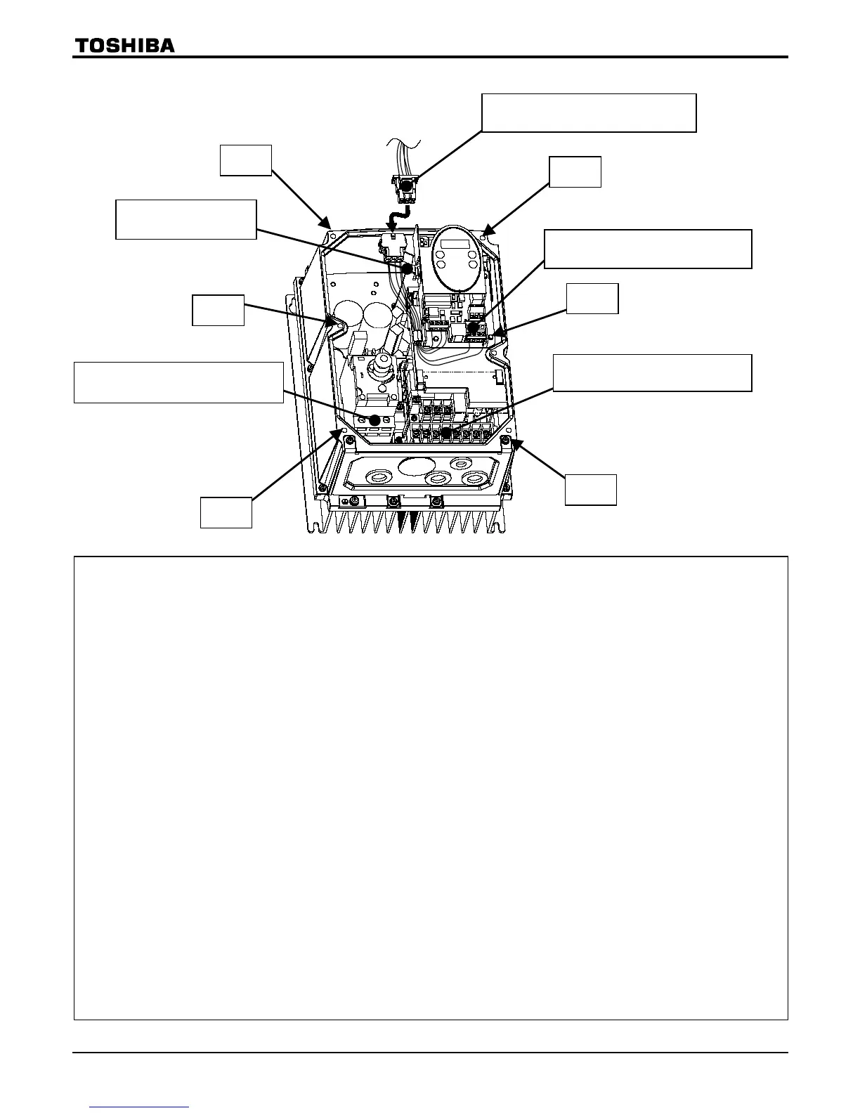
■Main circuit and control circuit terminal boards
How to remove the front cover
1. Shut off the supply of electricity from the main power supply, and turn the manual power ON-OFF switch to
the OFF position.
2. Ten minutes or more after turning off power, check to be sure that the CHARGE lamp is not lit.
3. Remove the 6 screws* (indicated by the arrows in the figure) around the front cover.
(* 4 screws for single/three-phase 200V-0.75kW models and smaller)
4. Pull the front cover slowly toward you to remove it and detach the control signal cable connector.
How to attach the front cover
1. Attach the control signal cable connector.
2. Attach the front cover.
3. Set and tighten the 6 screws* (indicated by the arrows in the figure) around the front cover.
(* 4 screws for single/three-phase 200V-0.75kW models and smaller)
Caution: Attach the front cover securely.
Or else it does not serve as a protector compliant with IP54.
On top of that, it may become impossible to operate the keys on the operation panel.
About the built-in cooling fan
The inverter has a built-in cooling fan. The cooling fan has a useful life of approximately 30,000 hours (2 to 3
years when operated continuously), so it needs to be replaced periodically.
(Single/three-phase 200V-0.75kW models and smaller are not equipped with cooling fans.)
If the cooling fan does not operate normally, the temperatures of the internal electrical components will rise
high, and as a result their lives will be shortened. So inspect it periodically.
About the useful life of the manual power ON-OFF switch
The manual power ON-OFF switch has a useful life of approximately 5 years (if operated 12 hours per day at
an average yearly ambient temperature of 30°C), so it needs to be replaced periodically.
Control circuit terminal board
Main circuit terminal board 2
Main circuit terminal board 1
Internal cooling fan
Motor output : U, V, W, PE
Internal DC section : P0, PA/+,
PB, PC/-
Power supply : R, S, T
(Single-phase : R, S)
Screw
Screw
Screw
Screw
Screw
Screw
Control signal cable connector
To front cover

 Loading...


