E6581225
4
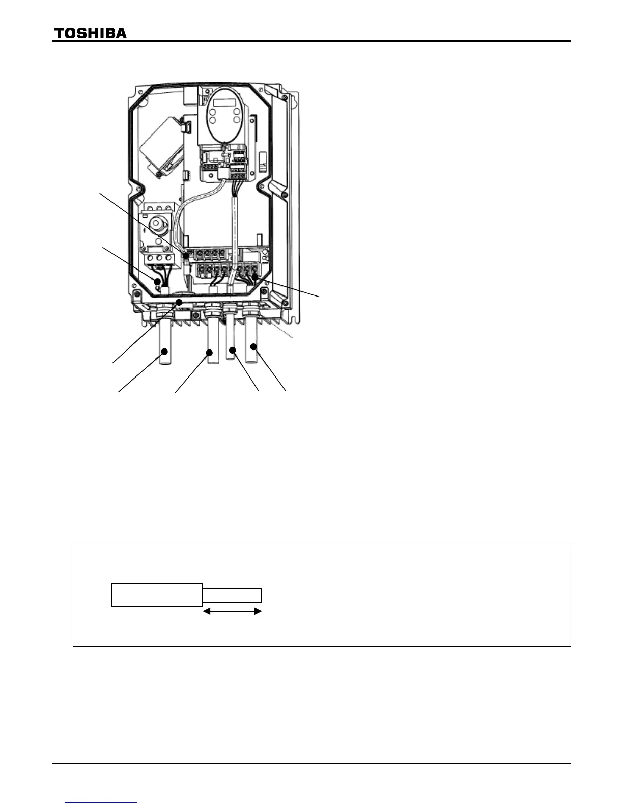
■Wiring diagram
(5)
(3)
(4)
(7)
(1)
(6)
(2)
(6)
(1) Input power cable
(2) Output cable
(3) Control cable
(4) Control resistor (optional) cable
(5) Wiring port plate
(6) Grounding terminal
(7) Optional communications device
interconnect cable
(Option)
Cautions
•
Circuit boards are exposed when the front cover is removed. Since high voltages are applied to some parts of
the circuit board, read Section 2.1, “Cautions on wiring,” of the instruction manual E6581158 carefully before
wiring.
When connecting cables, take care not to damage the circuit board with a screwdriver or a similar tool.
• To connect the power cable (to the manual power ON-OFF switch), torque the terminal screw to 1.7N·m
(recommended). (M4 screw)
• Never turn on the power ON-OFF switch before attaching the front cover.
Or you could get a shock.
The main circuit terminal board (input power cable) has terminals of a cable pinch type.
Before connecting a cable, strip off its sheath to a length of 10mm or so. Torque: 1.7N·m
Approx. 10mm

 Loading...


