3. Compliance with Connection
The opening of the branch circuit protective device may be an
indication that a fault current has been interrupted. To reduce the risk
of fire or electrical shock, current-carrying parts and other components
of the controller should be examined and replaced if damaged.
If burnout of the current element of an overload relay occurs, the
complete overload relay must be replaced.
(LE DÉCLENCHEMENT DU DISPOSITIF DE PROTECTION DU
CIRCUIT DE DÉRIVATION PEUT ÊTRE DÛ À UNE COUPURE QUI
RÉSULTE D'UN COURANT DE DÉFAUT. POUR LIMITER LE RISQUE
D'INCENDIE OU DE CHOC ÉLECTRIQUE, EXAMINER LES PIÈCES
PORTEUSES DE COURANT ET LES AUTRES ÉLÉMENTS DU
CONTRÔLEUR ET LES REMPLACER S'ILS SONT ENDOMMAGÉS.
EN CAS DE GRILLAGE DE L'ÉLÉMENT TRAVERSÉ PAR LE
COURANT DANS UN RELAIS DE SURCHARGE, LE RELAIS TOUT
ENTIER DOIT ÊTRE REMPLACÉ)
Use the UL conformed cables (Rating 75 °C or more, Use the copper conductors only.) to the main circuit terminals (R/L1,
S/L2, T/L3, U/T1, V/T2, W/T3).
For recommended tightening torque, see Table 1.
Use the ring terminal for the earth cables, see Table 2.
For recommended electric wire sizes, see Table 3,4.
Use the electric wire of Class1 for the control circuits.
For instruction in the United States, Integral solid state short circuit protection does not provide branch circuit protection.
Branch circuit protection must be provided in accordance with the National Electrical Code and any additional local codes.
For instruction in the Canada, Integral solid state short circuit protection does not provide branch circuit protection. Branch
circuit protection must be provided in accordance with the Canadian Electrical Code, Part I. .
(LA PROTECTION INTÉGRÉE CONTRE LES COURTSCIRCUITS N'ASSURE PAS LA PROTECTION DE LA
DÉRIVATION. LA PROTECTION DE LA DÉRIVATION DOIT ÊTRE EXÉCUTÉE CONFORMÉMENT AU CODE
CANADIEN DE L'ÉLECTRICITÉ, PREMIÈRE PARTIE.)
Table 1 Tighten the screws to specified torque
Recommended tightening torque for screws on the terminal board
N·m Ib·in
M3.5 1.0 8.9
M4 1.4 12.4
M5 2.4 20.8
M6 4.5 40.0
M4 (grounding terminal) 1.4 12.4
M5 (grounding terminal) 2.8 24.8
Table 2 Ring terminal sizes for earth cables
Earth Cable Sizes M4 (grounding terminal) M5 (grounding terminal)
AWG14 R2-4 [JIS standard] R2-5 [JIS standard]
AWG12 R5.5-4 [JIS standard] R5.5-5 [JIS standard]
AWG10 R5.5-4 [JIS standard] R5.5-5 [JIS standard]
E6582383
6
SCCR, Fuse and Wire sizes
Use the UL listed protective devices at connecting to power supply.
The VF-S15 short circuit current ratings have been obtained by shorting internal components. These ratings allow
proper coordination of short circuit protection.
Note) VFS15-4004PL ~ 4037PL don't comply with UL61800-5-1, comply with UL508C.
Note) The bold texts of the protective devices in the table 3 and 4 are the selection changes from the following.
- UL508C condition shown in E6581610REV01, E6581612REV03, E6582175REV01 or E6581928REV04 or their
previous revisions.
- UL61800-5-1 condition corrections shown in E6581610REV02, E6581612REV04 or E6582175REV02.
Suitable for use on a circuit capable of delivering not more than___X___rms symmetrical Amperes,___Y___Volts
maximum, when protected by___Z1___with a maximum rating of___Z2___.
(CONVIENT AUX CIRCUITS NON SUSCEPTIBLES DE DÉLIVRER PLUS DE___X___AMPÉRES SYMÉTRIQUES
EFFICACES, MAX. ___Y___V, AVEC PROTECTION PAR ___Z1___DE CALIBRE NOMINAL DE ___Z2___.)
Table 3 Standard SCCR condition of Fuses, Circuit breakers, line inductance and Wire sizes, with Enclosure
5 - - 12 14
VFS15-4004PL1
For the enclosure volume, it must be minimum 53L(Liter).
The enclosure mounting an inverter are a Type 1, 4(X) or 12 rated enclosure, only for the indoor usage.
Minimum enclosure volume allows for specified SCCR. Thermal requirements may require a larger enclosure.
The ampere rating of the short circuit protection devices in the table are maximum values.
Smaller ampere sizes can be used.
VF-S15_QS.indb 40VF-S15_QS.indb 40 2021/11/18 15:51:522021/11/18 15:51:52
41
E6582383
E6582383
5
3. Compliance with Connection
The opening of the branch circuit protective device may be an
indication that a fault current has been interrupted. To reduce the risk
of fire or electrical shock, current-carrying parts and other components
of the controller should be examined and replaced if damaged.
If burnout of the current element of an overload relay occurs, the
complete overload relay must be replaced.
(LE DÉCLENCHEMENT DU DISPOSITIF DE PROTECTION DU
CIRCUIT DE DÉRIVATION PEUT ÊTRE DÛ À UNE COUPURE QUI
RÉSULTE D'UN COURANT DE DÉFAUT. POUR LIMITER LE RISQUE
D'INCENDIE OU DE CHOC ÉLECTRIQUE, EXAMINER LES PIÈCES
PORTEUSES DE COURANT ET LES AUTRES ÉLÉMENTS DU
CONTRÔLEUR ET LES REMPLACER S'ILS SONT ENDOMMAGÉS.
EN CAS DE GRILLAGE DE L'ÉLÉMENT TRAVERSÉ PAR LE
COURANT DANS UN RELAIS DE SURCHARGE, LE RELAIS TOUT
ENTIER DOIT ÊTRE REMPLACÉ)
Use the UL conformed cables (Rating 75 °C or more, Use the copper conductors only.) to the main circuit terminals (R/L1,
S/L2, T/L3, U/T1, V/T2, W/T3).
For recommended tightening torque, see Table 1.
Use the ring terminal for the earth cables, see Table 2.
For recommended electric wire sizes, see Table 3,4.
Use the electric wire of Class1 for the control circuits.
For instruction in the United States, Integral solid state short circuit protection does not provide branch circuit protection.
Branch circuit protection must be provided in accordance with the National Electrical Code and any additional local codes.
For instruction in the Canada, Integral solid state short circuit protection does not provide branch circuit protection. Branch
circuit protection must be provided in accordance with the Canadian Electrical Code, Part I. .
(LA PROTECTION INTÉGRÉE CONTRE LES COURTSCIRCUITS N'ASSURE PAS LA PROTECTION DE LA
DÉRIVATION. LA PROTECTION DE LA DÉRIVATION DOIT ÊTRE EXÉCUTÉE CONFORMÉMENT AU CODE
CANADIEN DE L'ÉLECTRICITÉ, PREMIÈRE PARTIE.)
Table 1 Tighten the screws to specified torque
Recommended tightening torque for screws on the terminal board
N·m Ib·in
M3.5 1.0 8.9
M4 1.4 12.4
M5 2.4 20.8
M6 4.5 40.0
M4 (grounding terminal) 1.4 12.4
M5 (grounding terminal) 2.8 24.8
Table 2 Ring terminal sizes for earth cables
Earth Cable Sizes M4 (grounding terminal) M5 (grounding terminal)
AWG14 R2-4 [JIS standard] R2-5 [JIS standard]
AWG12 R5.5-4 [JIS standard] R5.5-5 [JIS standard]
AWG10 R5.5-4 [JIS standard] R5.5-5 [JIS standard]
SCCR, Fuse and Wire sizes
Use the UL listed protective devices at connecting to power supply.
The VF-S15 short circuit current ratings have been obtained by shorting internal components. These ratings allow
proper coordination of short circuit protection.
Note) VFS15-4004PL ~ 4037PL don't comply with UL61800-5-1, comply with UL508C.
Note) The bold texts of the protective devices in the table 3 and 4 are the selection changes from the following.
- UL508C condition shown in E6581610REV01, E6581612REV03, E6582175REV01 or E6581928REV04 or their
previous revisions.
- UL61800-5-1 condition corrections shown in E6581610REV02, E6581612REV04 or E6582175REV02.
Suitable for use on a circuit capable of delivering not more than___X___rms symmetrical Amperes,___Y___Volts
maximum, when protected by___Z1___with a maximum rating of___Z2___.
(CONVIENT AUX CIRCUITS NON SUSCEPTIBLES DE DÉLIVRER PLUS DE___X___AMPÉRES SYMÉTRIQUES
EFFICACES, MAX. ___Y___V, AVEC PROTECTION PAR ___Z1___DE CALIBRE NOMINAL DE ___Z2___.)
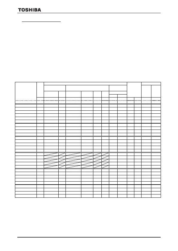
Table 3 Standard SCCR condition of Fuses, Circuit breakers, line inductance and Wire sizes, with Enclosure
With
□
(*1)
Type-Form
CR
Type-Form
Rating
Power
CR
Rating
SCCR
Min.
value
VFS15-2004PM
240
HGL36015
5
GV2P08
240 0.75
5
7 5 - - 14 14
VFS15-2022PM
240
HGL36020
5
GV3P18
240 5 5
25
5 - - 12 14
VFS15-2110PM
240
HGL36070
22
GV3P65
240 15
22
100
22 - - 6*2
8
(*6)
(*6)
(*6)
(*6)
(*6)
(*6)
VFS15S-2007PL
240
HGL36015
5
(*6)
GV3P13
240 2 5
(*6)
25
5
(*6)
- - 14 14
(*6)
(*6)
(*6)
(*6)
(*6)
(*6)
VFS15-4007PL
500
6 5 - - 14 14
VFS15-4037PL
500
25
5 - - 12 14
VFS15-4004PL1
480
HJL36015
5
GV2P07
480Y/277
1 5
6 5 - - 14 14
VFS15-4022PL1
480
HJL36015
5
GV2P14
480Y/277
5 5
15
5 - - 14 14
VFS15-4110PL
480
HJL36040
22
GV3P32
480Y/277
20
22
60
22 - - 8 10
For the enclosure volume, it must be minimum 53L(Liter).
The enclosure mounting an inverter are a Type 1, 4(X) or 12 rated enclosure, only for the indoor usage.
Minimum enclosure volume allows for specified SCCR. Thermal requirements may require a larger enclosure.
The ampere rating of the short circuit protection devices in the table are maximum values.
Smaller ampere sizes can be used.
VF-S15_QS.indb 41VF-S15_QS.indb 41 2021/11/18 15:51:522021/11/18 15:51:52
VF-S15_QS_CC2021.indd 41VF-S15_QS_CC2021.indd 41 2021/11/18 15:55:282021/11/18 15:55:28
 Loading...


