In case of using with a higher Short Circuit Current Ratings (SCCR) up to 100kA (up to 22kA for 600V class),
it is available by installing with the circuit breakers, GV
□
P or the fuses in the condition listed in Table 4.
Table 4 High SCCR condition of Fuses, Circuit breakers, line inductance and Wire sizes, with Enclosure
10 10
For the enclosure volume, it must be minimum 53L(Liter).
The enclosure mounting an inverter are a Type 1, 4(X) or 12 rated enclosure, only for the indoor usage.
Minimum enclosure volume allows for specified SCCR. Thermal requirements may require a larger enclosure.
The ampere rating of the short circuit protection devices in the table are maximum values.
Smaller ampere sizes can be used.
(*1) Use Class CC or J fast acting or time delay with any manufacturer, except VFS15-4004PL~4037PL.
(*2) For VFS15-4004PL~4037PL, Use Class J fast acting or time delay.
The manufacturer of the fuses must be "Cooper Bussmann" or "Mersen" (formerly, "Ferraz Shawmut") for the
compliance of UL standard.
(*3) The manufacturer of the listed circuit breaker is "Schneider Electric".
(*4) For GV2P and GV3P use, 480 V and 600V ratings are for Wye connected electrical distribution systems.
GV2P self-protected manual combination starter must be used with GV2GH7 insulating barrier to meet Type E rating.
GV3P self-protected manual combination starter must be used with GV3G66 + GVAM11 insulating barrier and auxiliary
contact to meet Type E rating. The GVAM11 provides a visual indication if the GV3P has tripped.
GV3P self-protected manual combination starter with connection by lugs that added the digit 6 to the end of reference
must be used with LAD96570 (2 pieces) + GVAM11 to meet Type E rating.
E6582383
8
UL61800-5-1 require publishing the standard Type E combination motor controller power rating since this is a basic
identification marking of type E devices.
However, when applied as an input overcurrent protective device for a drive, the rated current of the Type E
combination motor controller, not the rated power, is the key parameter for dimensioning.
GV
□
P Type E combination motor controllers are adjustable, their current range is shown on the adjustment dial and
their selection is based on the input current and not the power rating of the drive.
(*5) Reactor is RLW series of "MTE corporation" or from "Schneider Electric", do not substitute.
Reactor selection must be satisfied to the line inductance minimum values in the table.
(*6) Although SCCR is 5 kA, the thermal design is for 1 kA. For applying SCCR up to 5 kA, reduce the load or install the line
inductance not to exceed the rated input current.
Main and control circuit terminals
This diagram shows an example of wiring of the main and control circuit (in case of sink logic).
Standard connection diagram – SINK (Negative) (common: CC)
Main circuit power supply
Braking resistor (Option)
DC reactor (DCL)
*2 (option)
*1, *9
output
Low-speed
signal output
MCCB(2P)
External potentiometer (1k-10kΩ)
(or voltage signal between VIA and CC: 0-10V)
Forward run command
Reverse run command
Reset
Preset-speed command 1
Preset-speed command 2
Preset-speed command 3
Common
Speed reach
Signal output
Noise
Current signal: 4(0)-20mA
Voltage signal: 0-+10V
(or -10-+10V)
*3
*4 *4
STO
*8
3ph-240V class: three-phase 200-240V
-50/60Hz
1ph-240V class: single-phase 200-240V
-50/60Hz
3ph-500V class: three-phase 380-480V
-50/60Hz
3ph-600V class: three-phase 525-600V
*1: The T/L3 terminal is not provided for
single-phase models.
Use the R/L1 and S/L2/N terminals as input
terminals.
*2: The inverter is supplied with the PO and the
PA/+ terminals shorted by means of a
shorting bar.
Before installing the DC reactor (DCL),
remove the bar.
*3: When using the OUT output terminal in sink
logic mode, short the NO and CC terminals.
*4: When VIA or VIB terminal is used as logic
input terminal, refer to section 7.2.1.
*5: When backing up the control power supply,
an external DC24V power supply is required.
When using a communication option with the
external DC24V power supply, add a diode
between the external DC24V power supply
and +SU terminal. (Diode rating: 400V – 1.5A
or more)
Refer to section 2.3.2.
*6: Set the slide switch SW1 to SINK side.
Refer to section 2.3.2 for details.
Default setting is SINK side for Japan model,
PLC side for -W1 model.
*7: When STO terminal is used as compliance
with safety standards, refer to Safety function
manual (E6581860).
*8: Calibration is needed before using the meter.
Refer to section 5.1.
*9: When using 600V class, be sure to connect
an input reactor (ACL).
*10: 600V class have no built-in noise filter.
For sections,
refer to the instruction manual
E6581610(Japanese), E6581612(Japanese) or
VF-S15_QS.indb 42VF-S15_QS.indb 42 2021/11/18 15:51:532021/11/18 15:51:53
43
E6582383
E6582383
7
In case of using with a higher Short Circuit Current Ratings (SCCR) up to 100kA (up to 22kA for 600V class),
it is available by installing with the circuit breakers, GV
□
P or the fuses in the condition listed in Table 4.
Table 4 High SCCR condition of Fuses, Circuit breakers, line inductance and Wire sizes, with Enclosure
10 10
For the enclosure volume, it must be minimum 53L(Liter).
The enclosure mounting an inverter are a Type 1, 4(X) or 12 rated enclosure, only for the indoor usage.
Minimum enclosure volume allows for specified SCCR. Thermal requirements may require a larger enclosure.
The ampere rating of the short circuit protection devices in the table are maximum values.
Smaller ampere sizes can be used.
(*1) Use Class CC or J fast acting or time delay with any manufacturer, except VFS15-4004PL~4037PL.
(*2) For VFS15-4004PL~4037PL, Use Class J fast acting or time delay.
The manufacturer of the fuses must be "Cooper Bussmann" or "Mersen" (formerly, "Ferraz Shawmut") for the
compliance of UL standard.
(*3) The manufacturer of the listed circuit breaker is "Schneider Electric".
(*4) For GV2P and GV3P use, 480 V and 600V ratings are for Wye connected electrical distribution systems.
GV2P self-protected manual combination starter must be used with GV2GH7 insulating barrier to meet Type E rating.
GV3P self-protected manual combination starter must be used with GV3G66 + GVAM11 insulating barrier and auxiliary
contact to meet Type E rating. The GVAM11 provides a visual indication if the GV3P has tripped.
GV3P self-protected manual combination starter with connection by lugs that added the digit 6 to the end of reference
must be used with LAD96570 (2 pieces) + GVAM11 to meet Type E rating.
UL61800-5-1 require publishing the standard Type E combination motor controller power rating since this is a basic
identification marking of type E devices.
However, when applied as an input overcurrent protective device for a drive, the rated current of the Type E
combination motor controller, not the rated power, is the key parameter for dimensioning.
GV
□
P Type E combination motor controllers are adjustable, their current range is shown on the adjustment dial and
their selection is based on the input current and not the power rating of the drive.
(*5) Reactor is RLW series of "MTE corporation" or from "Schneider Electric", do not substitute.
Reactor selection must be satisfied to the line inductance minimum values in the table.
(*6) Although SCCR is 5 kA, the thermal design is for 1 kA. For applying SCCR up to 5 kA, reduce the load or install the line
inductance not to exceed the rated input current.
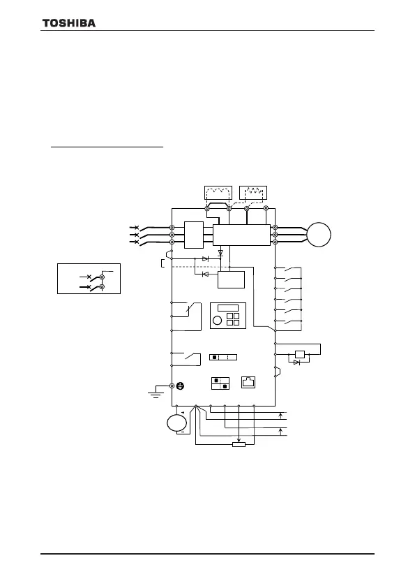
Main and control circuit terminals
This diagram shows an example of wiring of the main and control circuit (in case of sink logic).
Standard connection diagram – SINK (Negative) (common: CC)
Main circuit power supply
Braking resistor (Option)
Single
phase
power
supply
Fuse
MCCB
DC reactor (DCL)
*2 (option)
*1, *9
R/L1
S/L2
T/L3
function
output
Low-speed
signal output
MCCB(2P)
R/L1
Control power
supply
*5
Control
circuit
FLA
FLB
FLC
Operation panel
SW1 *6
SINK SOURCE
PLC
RS485
connector
RY
RC
1mA
(or 0(4)-20mA/0-10V)
External potentiometer (1k-10kΩ)
(or voltage signal between VIA and CC: 0-10V)
Forward run command
Reverse run command
Reset
Preset-speed command 1
Preset-speed command 2
Preset-speed command 3
Common
Speed reach
Signal output
Noise
filter
Power circuit
Motor
U/T1
V/T2
W/T3
Current signal: 4(0)-20mA
Voltage signal: 0-+10V
(or -10-+10V)
*3
*4 *4
STO
+SU
Frequency
meter
(ammeter)
Ry
*7
*8
3ph-240V class: three-phase 200-240V
-50/60Hz
1ph-240V class: single-phase 200-240V
-50/60Hz
3ph-500V class: three-phase 380-480V
-50/60Hz
3ph-600V class: three-phase 525-600V
*1: The T/L3 terminal is not provided for
single-phase models.
Use the R/L1 and S/L2/N terminals as input
terminals.
*2: The inverter is supplied with the PO and the
PA/+ terminals shorted by means of a
shorting bar.
Before installing the DC reactor (DCL),
remove the bar.
*3: When using the OUT output terminal in sink
logic mode, short the NO and CC terminals.
*4: When VIA or VIB terminal is used as logic
input terminal, refer to section 7.2.1.
*5: When backing up the control power supply,
an external DC24V power supply is required.
When using a communication option with the
external DC24V power supply, add a diode
between the external DC24V power supply
and +SU terminal. (Diode rating: 400V – 1.5A
or more)
Refer to section 2.3.2.
*6: Set the slide switch SW1 to SINK side.
Refer to section 2.3.2 for details.
Default setting is SINK side for Japan model,
PLC side for -W1 model.
*7: When STO terminal is used as compliance
with safety standards, refer to Safety function
manual (E6581860).
*8: Calibration is needed before using the meter.
Refer to section 5.1.
*9: When using 600V class, be sure to connect
an input reactor (ACL).
*10: 600V class have no built-in noise filter.
For sections,
refer to the instruction manual
E6581610(Japanese), E6581612(Japanese) or
E6582175(English)
*10
VF-S15_QS.indb 43VF-S15_QS.indb 43 2021/11/18 15:51:542021/11/18 15:51:54
VF-S15_QS_CC2021.indd 43VF-S15_QS_CC2021.indd 43 2021/11/18 15:55:312021/11/18 15:55:31

 Loading...


