48
E6582383
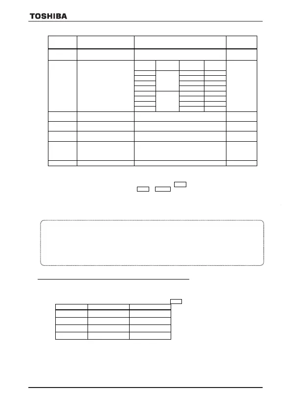
[Parameter setting]
Title Function Adjustment range
Default
setting
Motor electronic-thermal
protection level 1
10 – 100 (%) 100
Electronic-thermal
protection characteristic
selection
Setting
Overload
Overload
0
Standard
motor
1 valid valid
4
VF motor
(special
motor)
valid invalid
7 invalid valid
f173
Motor electronic-thermal
protection level 2
10 – 100 (%) / (A) 100
f607
Motor 150% overload
10 – 2400 (s)
300
Inverter overload detection
1: Temperature estimation
0
Electronic-thermal memory
0: Disabled (thr, f173)
1: Enabled (thr, f173)
2: Disabled (thr)
thr
0
Note) (Only for -W1 model)
aul must be set to default setting (1: Constant torque characteristic) for the compliance with UL standard.
1) Setting the electronic thermal protection characteristics selection
o
l
m
and motor electronic thermal protection level 1
t
h
r
, 2
f
1
7
3
The electronic thermal protection characteristics selection (olm) is used to enable or disable the motor overload trip
function (ol2) and the overload stall function.
While the inverter overload trip (ol1) will be in constantly detective operation, the motor overload trip (ol2) can be
selected using the parameter olm
Explanation of terms
Overload stall: This is an optimum function for equipment such as fans, pumps and blowers with variable torque
characteristics that the load current decreases as the operating speed decreases.
When the inverter detects an overload, this function automatically lowers the output frequency before the motor
overload trip (ol2) is activated. With this function, operation can be continued, without tripping, by operating
using a frequency balanced by load current.
Note: Do not use the overload stall function with loads having constant torque characteristics (such as conveyor
belts in which load current is fixed with no relation to speed).
[Using standard motors (other than motors intended for use with inverters)]
When a motor is used in the lower frequency range than the rated frequency, that will decrease the cooling effects for
the motor. This speeds up the start of overload detection operations when a standard motor is used in order to prevent
overheating.
Setting of electronic thermal protection characteristics selection olm
0 valid invalid
1 valid valid
2 invalid invalid
3 invalid valid
E6582383
14
×0.6
×1.0
Output frequency (Hz)
Output current reduction factor
[%]/[A]
0
Note: The motor overload protection start level is fixed at 30Hz.
×1.0
Output frequency (Hz)
Output current reduction factor
[%]
/
[A]
0
6Hz
×0.6
Note) The start level for motor overload reduction is fixed at 6 Hz.
Setting of motor electronic thermal protection level 1 thr (Same as f173)
When the capacity of the motor in use is smaller than the capacity of the inverter, or the rated current of the motor
is smaller than the rated current of the inverter, adjust thermal protection level 1 thr for the motor in
accordance with the motor's rated current.
[Using a VF motor (motor for use with inverter)]
Setting of electronic thermal protection characteristics selection olm
Setting value
Overload stall
valid invalid
valid valid
invalid invalid
invalid valid
VF motors (motors designed for use with inverters) can be used in frequency ranges lower than those for
standard motors, but their cooling efficiency decreases at frequencies below 6Hz.
Setting of motor electronic thermal protection level 1 thr (Same as f173)
If the capacity of the motor is smaller than the capacity of the inverter, or the rated current of the motor is
smaller than the rated current of the inverter, adjust the electronic thermal protection level 1 so that it fits
the motor's rated current.
2) Motor 150%-overload detection time
ff660077
Parameter f607 is used to set the time elapsed before the motor trips under a load of 150% (overload trip 2)
within a range of 10 to 2400 seconds.
3) Inverter overload detection method
ff663311
As this function is set to protect the inverter unit, this function cannot be turned off by parameter setting.
The inverter overload detection method can be selected using parameter f631 (Inverter overload detection method).
If the inverter overload trip function (ol1) is activated frequently, this can be improved by adjusting the stall operation
level f601 downward or increasing the acceleration time acc or deceleration time dec.
= (150%-60s)
Protection is given uniformly regardless of temperature by the 150%-60 sec overload curve.
= (Temperature estimation)
This parameter adjusts automatically overload protection, predicting the inverter internal temperature rise.
4) Electronic thermal memory
ff663322
When the power is OFF, it is possible to reset or maintain the overload totaling level.
This parameter's settings are applied both to the motor's electronic thermal memory and the electronic thermal memory
for inverter protection.
VF-S15_QS.indb 48VF-S15_QS.indb 48 2021/11/18 15:51:562021/11/18 15:51:56
E6582383
13
[Parameter setting]
Title Function Adjustment range
Default
setting
Motor electronic-thermal
protection level 1
10 – 100 (%) 100
Electronic-thermal
protection characteristic
selection
Setting
(special
motor)
valid invalid
7 invalid valid
f173
Motor electronic-thermal
protection level 2
10 – 100 (%) / (A) 100
f607
Motor 150% overload
10 – 2400 (s)
300
Inverter overload detection
1: Temperature estimation
0
Electronic-thermal memory
0: Disabled (thr, f173)
1: Enabled (thr, f173)
2: Disabled (thr)
Note) (Only for -W1 model)
aul must be set to default setting (1: Constant torque characteristic) for the compliance with UL standard.
1) Setting the electronic thermal protection characteristics selection
oollmm
and motor electronic thermal protection level 1
tthhrr
, 2
ff117733
The electronic thermal protection characteristics selection (olm) is used to enable or disable the motor overload trip
function (ol2) and the overload stall function.
While the inverter overload trip (ol1) will be in constantly detective operation, the motor overload trip (ol2) can be
selected using the parameter olm
Explanation of terms
Overload stall: This is an optimum function for equipment such as fans, pumps and blowers with variable torque
characteristics that the load current decreases as the operating speed decreases.
When the inverter detects an overload, this function automatically lowers the output frequency before the motor
overload trip (ol2) is activated. With this function, operation can be continued, without tripping, by operating
using a frequency balanced by load current.
Note: Do not use the overload stall function with loads having constant torque characteristics (such as conveyor
belts in which load current is fixed with no relation to speed).
[Using standard motors (other than motors intended for use with inverters)]
When a motor is used in the lower frequency range than the rated frequency, that will decrease the cooling effects for
the motor. This speeds up the start of overload detection operations when a standard motor is used in order to prevent
overheating.
Setting of electronic thermal protection characteristics selection olm
0 valid invalid
1 valid valid
2 invalid invalid
3 invalid valid
Output frequency (Hz)
Output current reduction factor
[%]/[A]
0
Note: The motor overload protection start level is fixed at 30Hz.
×1.0
Output frequency (Hz)
Output current reduction factor
[%]
/
[A]
0
6Hz
×0.6
Note) The start level for motor overload reduction is fixed at 6 Hz.
Setting of motor electronic thermal protection level 1 thr (Same as f173)
When the capacity of the motor in use is smaller than the capacity of the inverter, or the rated current of the motor
is smaller than the rated current of the inverter, adjust thermal protection level 1 thr for the motor in
accordance with the motor's rated current.
[Using a VF motor (motor for use with inverter)]
Setting of electronic thermal protection characteristics selection olm
Setting value
Overload stall
valid invalid
valid valid
invalid invalid
invalid valid
VF motors (motors designed for use with inverters) can be used in frequency ranges lower than those for
standard motors, but their cooling efficiency decreases at frequencies below 6Hz.
Setting of motor electronic thermal protection level 1 thr (Same as f173)
If the capacity of the motor is smaller than the capacity of the inverter, or the rated current of the motor is
smaller than the rated current of the inverter, adjust the electronic thermal protection level 1 so that it fits
the motor's rated current.
2) Motor 150%-overload detection time
f
Parameter f607 is used to set the time elapsed before the motor trips under a load of 150% (overload trip 2)
within a range of 10 to 2400 seconds.
3) Inverter overload detection method
f
As this function is set to protect the inverter unit, this function cannot be turned off by parameter setting.
The inverter overload detection method can be selected using parameter f631 (Inverter overload detection method).
If the inverter overload trip function (ol1) is activated frequently, this can be improved by adjusting the stall operation
level f601 downward or increasing the acceleration time acc or deceleration time dec.
= (150%-60s)
Protection is given uniformly regardless of temperature by the 150%-60 sec overload curve.
= (Temperature estimation)
This parameter adjusts automatically overload protection, predicting the inverter internal temperature rise.
4) Electronic thermal memory
f
When the power is OFF, it is possible to reset or maintain the overload totaling level.
This parameter's settings are applied both to the motor's electronic thermal memory and the electronic thermal memory
for inverter protection.
VF-S15_QS.indb 49VF-S15_QS.indb 49 2021/11/18 15:51:562021/11/18 15:51:56
VF-S15_QS_CC2021.indd 48VF-S15_QS_CC2021.indd 48 2021/11/18 15:55:332021/11/18 15:55:33

 Loading...


