6 of 12
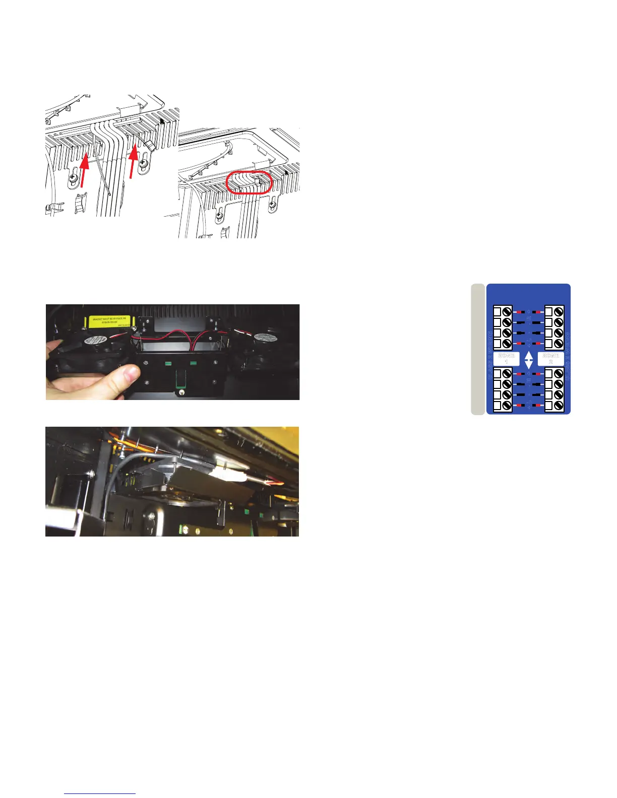
6. Verify that there is enough slack in the wires as you
connect them to the backplane.
7. Push the strain relief bracket back up, and tighten its
screws to hold it in place.
8. Use a zip tie to tie the wires to strain-relief bracket.
This will make it easier to reinstall the airflow
assembly.
9. Hook the Airflow Assembly back into position on the
chassis.
10.You will have to slide the left side in first, and behind
the cable for the top lighting panel.
11.Tighten the four screws until they push against the
metal of the chassis, such that the assembly cannot
be moved any longer (with the exception of the middle
flap.) The screws do not need to go in all the way;
they only need to push up against the chassis.
Note: The airflow assembly should not be disconnected,
unless you are replacing a damaged assembly. The
airflow assembly is required to maintain the temperatures
inside Playdium at acceptable levels.
To route cables through the bottom cable channel, loosen
the screws that hold its strain-relief bracket and slide it
until you can run your cables through. Remember to slide
the cover back into place and tighten its screws again
when you are done. Also remember to leave enough slack
on the cables to avoid any strain on the cables and
connectors.Finally, tighten the screws on the bracket to
hold it in place.
Step 6: Connect Playdium to the Broadband
Network
1. Locate the RJ-45 Ethernet cable for the broadband
connection.
2. Connect either end of the cable to a broadband
modem or router.
3. Route the free end of the cable into Playdium through
a cable channel.
4. Connect the free end of the cable to the port labeled
LAN on the backplane.
You will later configure the communications settings for
the broadband network so Playdium can contact the
TouchTunes server using this connection.
Step 7: Connect Audio Speakers to Playdium
1. Prepare your speaker wires by stripping the ends of
the 4 connector wires, exposing approximately 1/4” of
wire.
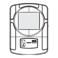
2. Locate the supplied four-slot Euroblock connector.
3. Loosen the screws along the
top of the connector using a
flat-head screwdriver, if
necessary.
4. Wire the ends of the speaker
wires to the Euroblock
connector using the figure
above as a guide.
5. Tighten the screws of the
slots to secure the speaker
cable to the connector.
Speaker Wiring
6. Insert the Euroblock connector into the connector
labeled Zone 1 or Zone 2 on the backplane.
Note: There are two connectors for each zone. These
connectors are wired in parallel. For more on how to wire
different sets of speakers, refer to the connection
diagram poster (packaged along with this guide.)
7. Route the free end of the cables out of Playdium
through the appropriate cable channel.
8. Connect the other end of the cables to the speakers,
ensuring that proper polarity is respected. Incorrect
connection can result in poor imaging and thin sound.
LEFT TOP
SIDE LIGHT
VOLUME PCB
SPEAKERS
R
-
+
L
+
-
ZONE
2
SPEAKERS
R
-
+
L
+
-
ZONE
1
CLASS 2 W
IRI
NG
CLASS 2 WIRING