3 -
38
Fig.
3-114
Fig. 3-
117
1
ENGI
NE
SERVICE
- Cylinder Block
..
El
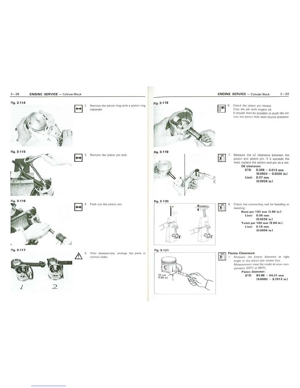
2.
Rem
ove
th
e piston ring with a piston ring
expand
er.
r::J 3. Remove
th
e piston p
11
1 bolt.
~
2
Push out
th
e pi
s1on
pin.
Alter
disassembly. arrange 1he pans m
cor
r
ect
orde
r.
Fig. 3-
118
Fig.
3-119
Fig.
3·
120
Fig
.
3-
121
E
NGINE
SERVICE
- Cylin
de
r Block
3-39
~
7
.
~
8
.
Check
th
e pi
s1o
n pin lirness.
Coat !he
pin
wuh
engine oil.
It should th
en
be
possible 10 push
1he
pin
into
the pis ton hole
whh
thu
mb
pressure.
Measure the
oi
l cl
ea
rance between the
pist
on
and pist
on
pin
. II it exceeds
1he
li
mit
re
place
th
e piston and pin as a set.
Oil clearance:
STD
0.008
-
0.012
mm
(0.0003
- 0.
0005
in.I
Limit
0.
07
mm
(0.
0028
in.)
Check
1he
connecting rod for bending
or
tw
is
ti
ng.
Bend per
10
0
mm
(3.94
in
.):
Lim
it
0.05
mm
(0.
0020
In
.)
Twist
per
100
mm
(3.
94
in.):
Li
n1
it 0.
16
n1m
(0.
0059
i
n.)
Piston
Clear
ance
I Measure tho piston diameter a 1 rig ht
angle to the piston pin center line.
Measurernen
t
1nu
st
be
made
at
room
tam
·
perature (20°C or 68°F)
Piston
diameter
:
S
TD
93.96
- 94.01
mm
(3.6992
-
3.
7012
in.)