6-
46
Fig. 6·
129
10
Fig. 6·
130
FUEL
SYSTE
M - Carburetor (General Countries)
\
2
3
•
5
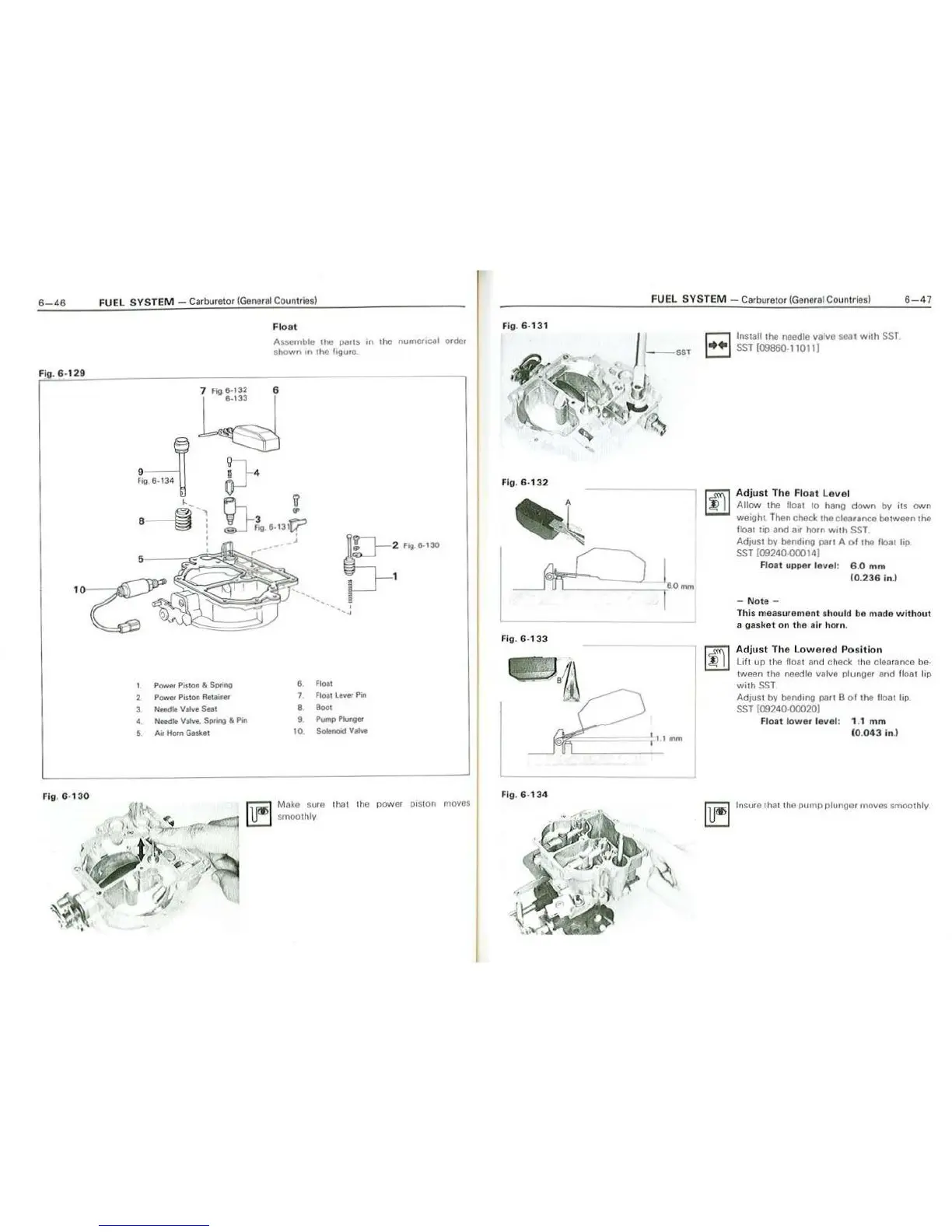
Float
Assomblo the parts m the
nume11cal
order
shown
on
the figure
7
Fog
8-132
6
8-133
0-
2
fog
8-130
1
Power
Pit
t
on
&
Spnng
a
Float
Power Pist
o.n
Reta
iner
7
F1oa1
lever
Pin
Nffodle
Valve
Seat
8
8001
Needle
Valve. Spnng & P.n
9
Pump
Plung<o
Ari
Hofn Gasket
\0
Solenoid
Vatve
fiiiil
Moke sure thal the power p1s1
on
movos
U!:J
smoothly.
Fig.
6· 131
Fig.
6-
132
fig.
6-133
,
f i
g.
6·
134
")
~Si~
FUEL
SYSTEM
- Carburetor (General Countries)
6-47
I
(Omm
t 1 I
mm
I
r::1
Install the needle valvo seat
with
SST
i:::J
SST
109860-11011)
~
Adjust
The
Float
Level
Allow
tho float
10
hang
down
by its own
we1ghL
Then check the clearance between the
float
top
and air horn
with
SST
Adiust
by
bending
pan
A
ol
the float
lip
SST (09240-00014)
Float
upper
level
:
6.
0mm
10.236
in
.)
-
Note
-
This measurement should
bo
nlnde
without
a gasket
on
th
e
air
horn.
I
~
Adjust
T
he
L
owe
r
ed
Position
Lift
up
the
fl
oa
t and check tho clearance be·
tween tho needle valve plunger and lloat lip
wit
h
SST
AdJUSt
by bending
PO
ii
B
ol
tho
1100
1 lip.
SST
(09240·00020)
Float
lower
level
: 1.1
mm
(0.
043
in.)
l
lf'>
l Insure that
th
o pump plunger moves smoothly
 Loading...