8
-6
Fig. 8 -11
Fig.
8-
12
Fig.
8-13
IGNITION
SYSTEM
- On-Vehicle Inspection
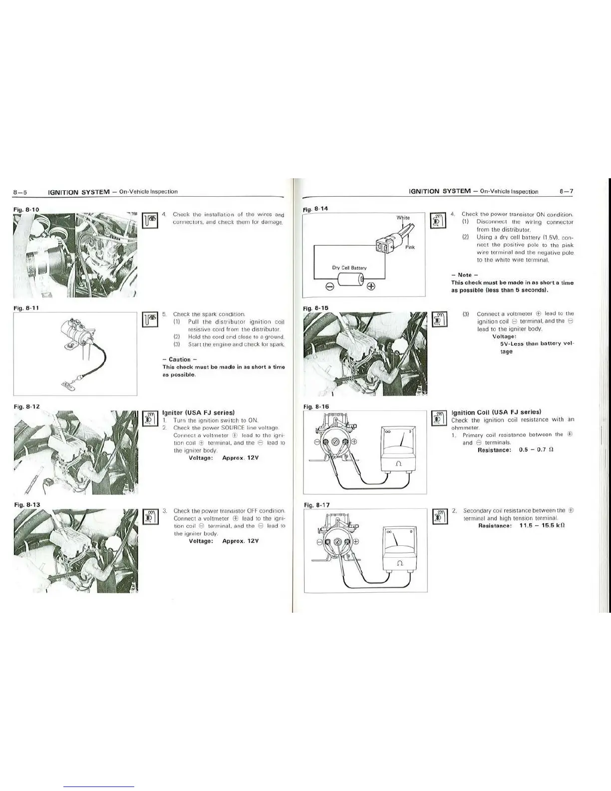
4. Check
1he
installation o l
th
e wires and
connector
s.
a
nd
ch
ec
k them 1
01
damage,
Check the spark cond
iti
on.
(ti
Pu
ll
the di
st
ri
but
or
igni
t
ion
coil
resistive cord from
th
e distribu101
{2) Hold the cord end close 10 a grou
nd
.
{3)
S1a1t
the engine and check for
spa
rk.
- Caution -
This check
must
be
made
in
as
sho
rt
o time
as possible.
Ign
ite
r
{USA
FJ
series)
I. Turn
th
e i
gnit
i
on
switch
to
ON
2. Check the
powe
r
SOU
RC
E line voltage
Connect a
vo
ltmeto•
"1
1 lead to the
1gni·
uon coil
J;
t
er
minal. and the B lead ta
the igniter body
Voltage:
Ap,prox.
12V
Check the power transistor
OFF
condition
Connect a voltmeter © lead to the
ig
ni·
liOll
co
il 9 terrrunal. and the $ l
ea
d
tO
t
he
19ni
te1 body.
Voltage:
App
rox.
1
2V
fig. 8-
14
Ory
Ctlf
Ba
tt
ery
e
\..__
_.:>}
Fig. 8-
16
F
ig
.
8-17
00
.n
IGNITION
SYSTEM
- On-Vehi
cle
Insp
ec
tion 8
-7
•
•
~
4
.
Ch
ec
k the power trMs1stor ON condition.
(1)
Disconnect the wiring connector
from 1
he
distributor.
(2) Usi
ng
a dry cell baue1y (1.5VI. con·
no
ct the positive pole to the pink
wire
terminal and lhe
ne
gative pole
to
the white wire
te
rminal.
-
Note
-
This
check
mus
t bo made
in
as short a
ti
me
as possible (less than 5 seconds>.
(3)
Connect a vo
lt
meter
Ee
lead
to
the
ign
ition coil e termi
na
l. and the e
lead to the igniter body.
Volt
age:
5V
·Lcss than
battery
vo
l·
1age
Ignition
C
oi
l
{USA
FJ
series)
Check the ignition coil res
is
tance with an
ohmmeter .
1. Primary
co
il resistance between t
he
$
and e termi
na
l
s.
Resistance:
0.5
- 0. 7
fl
Secondary
coo
l r
es
istance between the ®
te
rm
inal
and
high
tension
terininal.
Resistance:
11.5
-
15
.5 k
fl