Do you have a question about the Toyota 3B and is the answer not in the manual?
Lists the Toyota models applicable to this repair manual.
Provides guidance on navigating and utilizing the manual's features.
Outlines general guidelines and precautions for performing repairs.
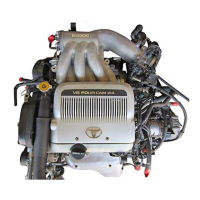
Provides a general overview of the engine.
Guides on diagnosing issues with diesel engines.
Diagnosing electrical systems for 3B engines.
Diagnosing electrical systems for 11B and 14B engines.
Procedures for adjusting and tuning the engine.
Steps for checking compression on B and 3B engines.
Steps for checking compression on 11B and 14B engines.
Information and procedures related to the cylinder head.
Details on timing gears and camshaft inspection and replacement.
Information and procedures for the cylinder block.
Troubleshooting steps for cold start issues in 3B engines.
Troubleshooting steps for cold start issues in 11B and 14B engines.
Instructions for cleaning paper type air filters.
Instructions for cleaning oil bath type air filters.
Steps for removing the cylinder head assembly.
Steps to remove injection nozzles for B and 3B engines.
Procedure to remove glow plugs for B and 3B engines.
Procedure to measure cylinder compression pressure using SST.
Procedure to measure cylinder compression pressure using SST.
Exploded view and list of cylinder head components.
Steps for removing the cylinder head assembly.
Procedure to remove valves from the cylinder head.
Steps for cleaning and inspecting cylinder head components.
Procedure to clean piston tops and cylinder block surfaces.
Procedure to check cylinder head flatness for warpage.
Method to inspect the cylinder head for cracks using dye penetrant.
Steps for removing and installing new valve guide bushings.
Procedure for inspecting and grinding valves to correct face angle and margin.
Exploded view of cylinder block components.
General hints and steps for cylinder block assembly.
Procedure to install combustion chambers for B and 3B engines.
Steps for installing the cylinder head with gasket.
Procedure for torquing cylinder head bolts in progressive steps.
Exploded view of timing gears and camshaft components.
Steps for removing timing gears and camshaft.
Procedure to set cylinder No. 1 to TDC/compression.
Steps to remove the valve rocker shaft assembly.
Procedures for checking camshaft circle runout, lobe height, journal diameter, and thrust clearance.
Exploded view of cylinder block components.
Steps for disassembling the cylinder block.
Steps to remove the oil pan and oil pump assembly.
Measuring connecting rod thrust clearance using a dial indicator.
Procedures for inspecting the cylinder block surface and bore.
Checking cylinder block surface flatness for warpage.
Measuring cylinder bore diameter at multiple points.
Procedure to remove cylinder ridge using a reamer.
Steps for disassembling the piston and connecting rod assemblies.
Steps to remove piston compression and oil rings.
Steps for cleaning and inspecting piston and rod assemblies.
Procedure to clean carbon and grooves from pistons.
Measuring piston diameter and calculating oil clearance.
Measuring piston ring end gap in the cylinder bore.
Checking piston pin fit in the piston at elevated temperature.
Checking connecting rod alignment and maximum bend.
Steps for boring cylinders to accommodate oversized pistons.
Process of boring and honing cylinders to specified dimensions.
Measuring crankshaft circle runout using a dial indicator.
Measuring main journal and crank pin diameters for wear.
Inspecting camshaft oil clearance and repairing bearings.
Steps for removing and installing new camshaft bearings.
Measuring valve lifter bore diameter and lifter diameter for oil clearance.
General hints and steps for cylinder block assembly.
Steps to install main bearings into the cylinder block and caps.
General description of the fuel system.
Procedure for replacing the fuel filter.
Information on injection nozzles for B and 3B engines.
Information on injection nozzles for 11B and 14B engines.
Details on the injection pump.
Procedure to inspect the fuel heater resistance.
Checking continuity of the vacuum switch.
Steps for removing and testing injection nozzles.
Procedure to remove injection pipes.
Steps to disassemble, clean, and test the injection nozzle.
Steps to disassemble the injection nozzle.
Procedure for cleaning injection nozzles.
Steps for removing and testing injection nozzles.
Procedure to remove injection pipes.
Steps to disassemble, clean, and test the injection nozzle.
Steps to disassemble the injection nozzle.
Procedure for cleaning injection nozzles.
Steps for removing the injection pump.
General hints and steps for assembling the injection pump.
Procedure to install the regulator valve.
Steps to install the feed pump components.
Pre-test checks and preparation for injection pump adjustment.
Ensures proper setup before injection pump adjustment.
Steps for assembling the injection pump, including sleeve plug subassembly.
Procedure to install the regulator valve.
Steps to install the feed pump components.
General description of the engine's cooling system.
Troubleshooting common cooling system problems.
Procedures for checking and replacing engine coolant.
Information regarding the water pump.
Details on the thermostat and its operation.
Information about the radiator's function.
Table listing common cooling system problems, causes, and remedies.
Procedure to check the engine coolant level in the reserve tank.
Steps to inspect the quality and condition of the engine coolant.
Steps for removing the water pump assembly.
Checking the water pump bearing for smooth operation.
Inspecting the fluid coupling for damage and leakage.
Steps for installing the water pump with gasket and bolts.
Steps to remove the thermostat from the water outlet.
Instructions for cleaning the radiator core.
Procedures to inspect the radiator cap and cooling system for leaks.
Method to test the cooling system for leaks under pressure.
General description of the engine lubrication system.
Troubleshooting common lubrication system issues.
Procedures for checking engine oil pressure.
Steps for replacing engine oil and the oil filter.
Information on the oil pump assembly.
Details on the oil cooler and relief valve.
Information about oil nozzles and check valves.
Table of common lubrication problems, causes, and remedies.
Procedure to check the engine oil quality.
Measuring oil pressure at idle and specified RPM.
Procedure to drain the engine oil.
Steps to remove and install a new oil filter using SST.
Steps for removing the oil pump assembly.
Exploded view of oil pump components.
Steps for disassembling the oil pump.
Steps to remove the drive and driven rotors.
Exploded view of oil cooler and relief valve components.
Steps for removing the oil cooler and relief valve.
Checking relief valve operation by its weight.
Checking the oil cooler for damage or clogging.
Exploded view of oil nozzles and check valve components.
Steps for removing oil nozzles and check valve.
Steps to remove oil nozzles using SST.
Checking if the check valve is stuck.
Checking oil nozzles for damage or clogging.
Steps for installing oil nozzles and check valve.
Steps to install oil nozzles with O-ring and alignment.
Information on the pre-heating system for B and 3B engines.
Information on the pre-heating system for 11B and 14B engines.
Troubleshooting common starting system issues.
Electrical schematic of the starting system circuit.
Details regarding the starter motor.
Information on starter relays for BB, BU, and BY models.
Information on starter relays for the BJ model.
Electrical schematic diagram for the super glow type pre-heating system.
Inspection procedures for the pre-heating timer.
Steps to measure pre-heating indicator light timing and voltage.
Inspection of starter relays for BB and BU models.
Inspection of starter relays for the BJ model.
Electrical schematic for the fixed delay type pre-heating system.
Inspection procedures for the pre-heating timer.
Measuring pre-heating timer lighting time and voltage.
Electrical schematic diagram for the 11B and 14B pre-heating system.
Inspection procedures for the pre-heating timer.
Measuring pre-heating indicator light duration.
Inspection of intake heater relay continuity and operation.
Checking the intake heater for continuity.
Table of starting system problems, causes, and remedies.
Electrical schematic diagram of the starting system.
Exploded view of starter motor components.
Steps for disassembling the starter motor.
Steps to remove starter housing, clutch assembly, and gear.
Steps to remove the starter brush holder.
Inspection procedures for starter components like commutator.
Checking commutator segments for open circuits.
Checking commutator for ground faults.
Checking and correcting commutator undercut depth.
Checking field coil for open circuits.
Measuring brush length and checking for wear.
Checking brush holder insulation for continuity.
Checking gear teeth on pinion, idler, and clutch assembly for wear.
Checking bearings for resistance or sticking.
Diagnostic tests for the starter's magnetic switch.
Testing the starter's full-in coil for open circuits.
Testing the starter's hold-in coil for open circuits.
Steps for assembling the starter motor.
Procedure to install the armature into the field frame.
Steps to install the starter brush holder.
Tests to evaluate starter performance under no-load conditions.
Testing the starter's pull-in coil function.
Testing the starter's hold-in coil function.
Inspection procedures for starter relays for BB, BU, and BY models.
Checking starter relay continuity and operation.
Inspection procedures for starter relays for the BJ model.
Checking starter relay continuity and operation.
Safety precautions related to the charging system.
Troubleshooting common charging system problems.
Electrical schematic of the charging system circuit.
Procedures for inspecting the charging system on the vehicle.
Information regarding the alternator.
General precautions for working with the charging system.
Table of charging system problems, causes, and remedies.
Electrical schematic diagrams for the charging system.
Procedure to check battery cell specific gravity.
Visual inspection and deflection check of the drive belt.
Checking alternator wiring condition and listening for abnormal noises.
Testing the charge warning light operation.
Testing the charging circuit without electrical load.
Exploded view of alternator components.
Steps for disassembling the alternator.
Steps to remove the rectifier end frame.
Procedure to remove the rotor from the drive end frame.
Inspection and repair procedures for alternator rotor and stator.
Inspection of alternator rotor for circuit issues.
Inspection of alternator stator for circuit issues.
Inspection and replacement of alternator brushes.
Inspection of the positive side rectifier.
Inspection of the negative side rectifier.
Inspection and replacement of alternator bearings.
Steps for removing and installing a new rear bearing.
Steps for assembling the alternator.
Procedure to install the rotor into the drive end frame.
Procedure for installing the pulley and nut with specified torque.
Specifications for engine mechanical components.
Specifications for the fuel system.
Specifications for the cooling system.
Specifications for the lubrication system.
Specifications for the starting system.
Specifications for the charging system.
Specifications for engine tune-up, oil capacity, and battery.
Engine tune-up specifications including coolant capacity.
Engine oil capacity specifications for drain and refill.
Battery specific gravity specifications.
Specifications for valve springs.
Specifications for rocker arms and shafts.
Specifications for push rods.
Specifications for the camshaft.
Specifications for connecting rods.
Specifications for the crankshaft.
Specifications for pistons and piston rings.
Table of specified torque values for various engine components.
Specifications for injection nozzles.
Specifications for injection nozzles.
Specifications for the injection pump.
Pre-test checks and preparation for injection pump adjustment.
Pre-setting specifications for injection pump.
Continuation of injection pump adjustment and test specifications.
Pre-setting specifications for overflow volume and automatic timer.
Continuation of injection pump adjustment and test specifications.
Continuation of injection pump adjustment and test specifications.
Continuation of injection pump adjustment and test specifications.
Table of specified torque values for various engine components.
Specifications for cooling system components.
Specifications for lubrication system components.
Specifications for pre-heating system and starter.
Specifications for battery, alternator, and regulator.
General information on standard bolt torque specifications.
Guidance on identifying bolt strength classes.
Table of specified torque values for standard bolts.
List of Special Service Tools (SST) used for vehicle inspections and repairs.
List of Special Service Materials (SSM) used in repairs.
List of Special Service Tools (SST) with classification.
Classification system for Special Service Tools (SST).
Continuation of the list of Special Service Tools (SST).
Continuation of the list of Special Service Tools (SST).
Continuation of the list of Special Service Tools (SST).
Continuation of the list of Special Service Tools (SST).
List of Special Service Materials (SSM) with usage details.
| Bore x Stroke | 102 mm x 105 mm |
|---|---|
| Fuel System | Indirect injection |
| Cooling System | Water-cooled |
| Valvetrain | OHV, 2 valves per cylinder |
| Aspiration | Naturally aspirated |
| Displacement | 3.4 L (3, 431 cc) |
| Torque | 216 Nm (159 lb-ft) at 2000 rpm |
| Engine Type | Diesel, four-stroke |