Toyota Orderpicker Model
7BPUE
15
Service Manual
Section
8.
Wire Guidance
Installation
1.
Clean the encoder shaft. Apply retaining
compound (Loctite
609)
to the encoder
shaft.
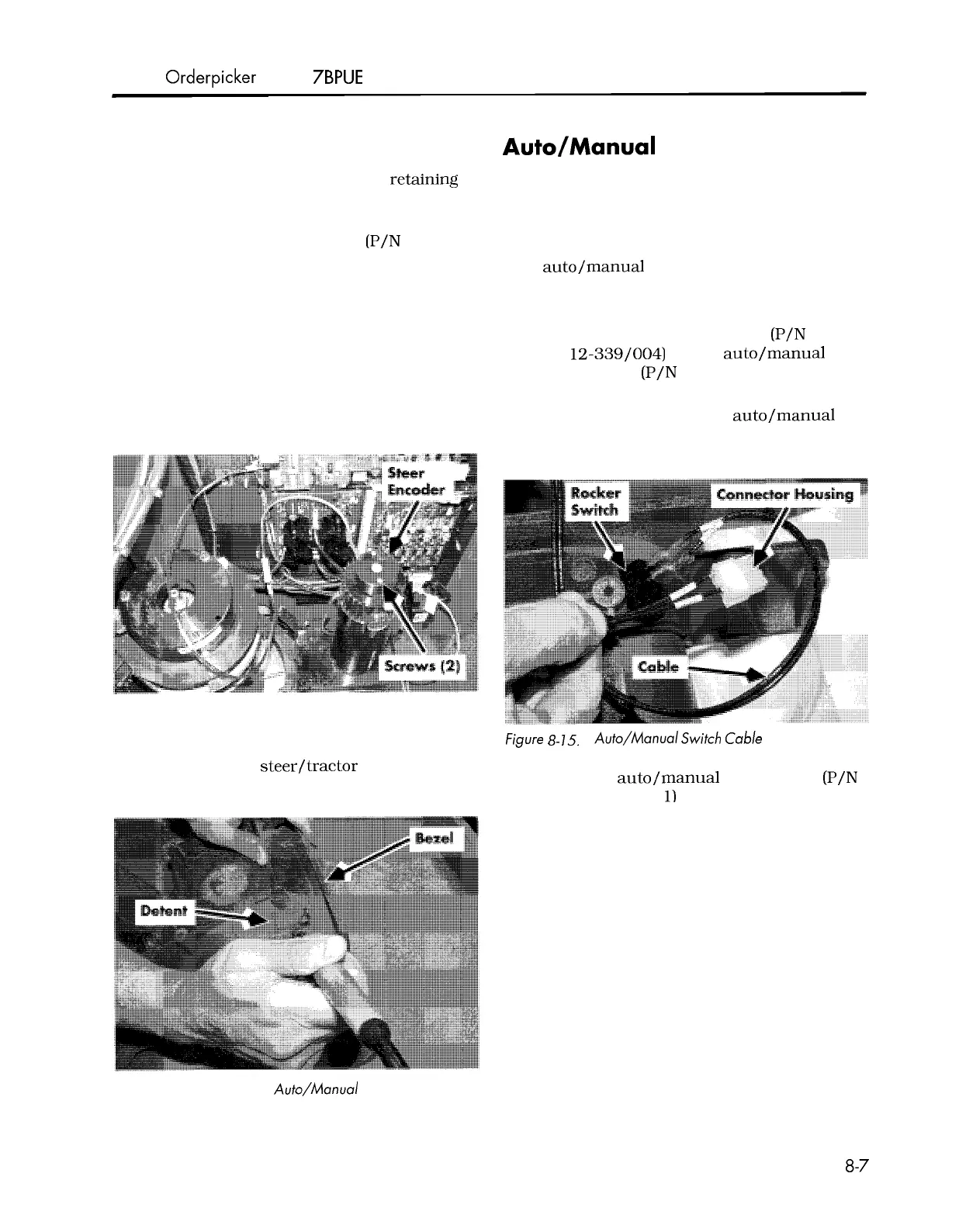
2.
Install the steer encoder kit (P/N
00590
-
45880
-
7
1)
on the shaft.
3.
Install the encoder cover and the two
mounting screws.
4.
Secure the encoder to the motor with the
two screws provided with the steer
encoder. See Figure
8
-
13.
5.
Route the cable from the encoder down the
side of the motor and connect to cable
JH7.
Figure
8
-
13.
Steer Encoder, Installed
Install Kit Components
Auto/Manual
Switch
1.
Remove the operator console cover.
2.
Remove the bezel.
3.
From the backside of the bezel, use a hot
knife to cut out the detent for the
auto/manual switch. See Figure
8
-
14.
4.
Place the rocker switch orange
-
side
-
up in
the bezel.
5.
Install the connector housing (P/N
1
-
0 12-339/004)
on the auto/manual
switch cable (P/N
00590
-
45865
-
7
1).
See
Figure
8
-
1
5.
6.
Connect the cable to the auto/manual
switch. See Figure
8
-
15.
Then connect to
the carriage manager.
6.
Route that cable along the existing wiring
Figure
8-
15.
Auto/Manual Switch Cable
to
PT6
on the steer/tractor manager.
7.
Place the auto/manual switch decal (P/N
7.
Use cable ties as necessary.
00590
-
45783
-
7
1)
on the front side of the
bezel. See Figure
8
-
16.
Figure
8
-
14.
Cutting the Auto/Manual Switch Detenf
00700
-
CL222
-
05,
1
5 March 2005
 Loading...