This manual outlines the service procedures for the TOYOTA ELECTRIC POWERED FORKLIFT 7FBE10 to 20 series, covering models as of February 2003. It serves as a comprehensive guide for providing quick and accurate servicing for these forklift models. Users should be aware that minor discrepancies may exist between the manual's descriptions and actual vehicles due to ongoing design and specification changes. Any subsequent modifications will be communicated via Toyota Industrial Equipment Parts & Service News.
The manual is structured into several sections, each dedicated to a specific component or system of the forklift. These sections include:
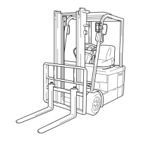
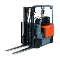
- General (0): Provides an overview of the vehicle, including exterior views, model information, frame numbers, and instructions on how to use the manual. It also covers terminology, abbreviations, SI units, operating tips, general instructions, jack-up points, hoisting procedures, wire rope suspension angle lists, safe load information, member weights, towing procedures, electrical parts inspection, and notes on SAS functions. Additionally, it details standard bolt and nut tightening torques, bolt strength class identification, and precoated bolts.
- Battery (1): Focuses on the battery system.
- Charger (OPT) (2): Covers the optional charger unit.
- Controller (3): Details the vehicle's control system.
- Multi-Display Functions (4): Explains the various functions of the multi-display unit.
- Troubleshooting (5): Provides guidance on diagnosing and resolving common issues.
- Motor (6): Describes the motor components and their maintenance.
- Drive Unit & Front Axle (7): Covers the drive unit and front axle assembly.
- Rear Axle (8): Focuses on the rear axle.
- Steering (9): Details the steering system.
- Brake (10): Explains the braking system.
- Body & Frame (11): Covers the vehicle's body and frame structure.
- Material Handling System (12): Describes the components involved in material handling.
- Mast (13): Focuses on the mast assembly.
- Cylinder (14): Details the hydraulic cylinders.
- Oil Pump (15): Covers the oil pump.
- Oil Control Valve (16): Explains the oil control valve.
- SAS Functions (OPT) (17): Addresses the optional System of Active Stability (SAS) functions.
- Appendix (18): Contains supplementary information.
How to Use This Manual:
Operating procedures are explained using two patterns:
- Pattern A: Each step of an operation is accompanied by its own illustration.
- Pattern B: The entire operation is illustrated with step numbers, followed by cautions, notes, and point operations. Some step numbers may be omitted in illustrations. Point operations provide detailed explanations with illustrations for specific steps, such as disassembly instructions or inspection limits.
Terminology:
- CAUTION: Highlights important matters where negligence may lead to accidents. Strict adherence is required.
- NOTE: Points out important items, potential accident causes, or specific considerations during operation.
- Standard: Refers to the allowable range for inspection or adjustment.
- Limit: Indicates the maximum or minimum permissible value during inspection or adjustment.
SI Units:
The manual exclusively uses SI (International System of Units) to standardize technical communication. Conversion rates from conventional units to SI units are provided for force, torque, pressure, revolving speed, spring constant, volume, power, heat quantity, and specific fuel consumption. Users are advised to convert units as necessary, following the provided conversion rate table.
Operating Tips and General Instructions:
- Skillful Operation: Before starting any operation, ensure all necessary tools, measuring instruments (circuit tester, megohmmeter, oil pressure gauge), and Special Service Tools (SSTs) are prepared. Always check cable colors and wiring before disconnecting any wires. When overhauling complex or functional parts, organize them neatly to prevent confusion. For precision parts like control valves, use clean tools and work in a clean environment. Follow specified procedures for disassembly, inspection, and reassembly. Always replace gaskets, packing, O-rings, self-locking nuts, and cotter pins with new ones after disassembly. Use genuine Toyota parts and specified bolts/nuts, observing tightening torques. If no torque is specified, use the value from the "standard tightening torque table."
- Protection of Functional Parts (Battery Operated Vehicles): Before reconnecting the battery plug after inspection or maintenance, thoroughly check all connectors for proper connection. Improper connections, especially those related to controllers, can damage internal components.
- Defect Status Check: Before disassembling or replacing parts, confirm that such action is indeed necessary for the identified defect.
- Waste Fluid Disposal: Always use appropriate containers for draining waste fluids. Improper disposal of oil, fuel, coolant, oil filters, batteries, or other harmful substances can harm human health and the environment. Collect and sort waste properly, and contact specialized companies for disposal.
Jack-Up and Hoisting Procedures:
- Jack-Up Point: Always unload the fork and park the vehicle on a flat surface before jacking. Use a jack with sufficient capacity at the specified jack-up points. Never jack at other points. Always support the jacked-up vehicle with wooden blocks at specified points; relying solely on the jack is dangerous. Never place any part of your body under a jacked-up vehicle.
- Hoisting the Vehicle: Always use the specified hoist attachment section and method. Hoisting from any other section is extremely dangerous.
Towing the Vehicle:
- Lift the rear wheels for towing.
- The towing speed must not exceed the forklift's maximum traveling speed.
- Before towing, set the key switch to OFF and the direction switch to the neutral position.
- Remove the fork or secure it to prevent contact with the ground due to bouncing.
Electrical Parts Inspection:
- Always disconnect the battery plug before inspecting or servicing electrical parts.
- Handle electronic parts with care: avoid impact, high temperatures, moisture, and touching connector terminals to prevent deformation or damage from static electricity.
- Use a circuit tester appropriate for the measurement. Analog testers are useful for observing movement, while digital testers provide more accurate readings. Be aware that measurement results may differ between analog and digital types due to varying internal circuits and power supply voltages. Always use the range specified in the repair manual for measurement.
Notes on SAS (System of Active Stability):
- For detailed explanations of SAS functions and operation, refer to "New Model Feature 7FBE10 to 20 Pub. No.PE314."
- Consult page 17-6 of this manual for repair work before servicing.
- If any SAS-related part is repaired or replaced, perform necessary matching to ensure proper SAS function (see page 4-47).
- Always operate the vehicle carefully, understanding the differences in control features with and without SAS.
- Many precision valves are used in the SAS oil control valves. When disassembling or replacing hydraulic parts, ensure they are thoroughly cleaned before installation. Regular hydraulic oil changes are also crucial.
- The vehicle is equipped with high-precision electronic devices. Modifications to electrical parts can cause vehicle failure. Use only genuine Toyota parts for replacement and installation of electrical components.
Standard Bolt & Nut Tightening Torque:
The manual provides charts and tables to determine standard tightening torques for bolts and nuts. Users should identify the bolt strength class from the table and then find the corresponding tightening torque. Nut tightening torque can be determined from its corresponding bolt type.
Precoated Bolts:
Precoated bolts should not be replaced or restored if they have been removed or moved (loosened or tightened). For torque checks, tighten the bolt to the lower limit of the allowable range; if it moves, retighten it according to the specified steps. To reuse precoated bolts, wash the bolt and threaded hole, dry them completely, and apply a specified seal lock agent to the threaded portion.
High Pressure Hose Fitting Tightening Torque:
When connecting a high-pressure hose, clean the hose fitting and nipple contact surfaces to remove foreign matter and dirt. Check for dents or damage before installation. Hold the hose to align the fitting with the nipple and tighten it. The maximum tightening torque must not exceed twice the standard tightening torque.