Do you have a question about the Toyota ESP9000 and is the answer not in the manual?
Checks for power supply issues, focusing on cord and connections.
Troubleshoots 'SEWING MOTOR' error, checking power, connectors, and resistance.
Troubleshoots 'X MOTOR' error, checking power, connectors, and resistance.
Troubleshoots 'Y MOTOR' error, checking power, connectors, and resistance.
Troubleshoots 'NEEDLE CASE ERROR', checking connectors and resistance.
Addresses issues with the holder not returning to home position, checking sensors and voltage.
Solves thread coming off the needle by checking tensions, thread path, and hook tip.
Rectifies skipped stitches by checking needle timing, clearance, and thread path.
Resolves needle thread breakage by inspecting thread path, tension, and component edges.
Fixes bobbin thread breaks by checking needle plate, rotary hook, and bobbin case for burrs.
Addresses needle breaks by checking clamping, needle condition, and starting position.
Fixes thread wiper hook malfunction by checking cleaning, lever deformation, connectors, and resistance.
Solves thread trimming failures by checking lint buildup, trim timing, and thread catcher position.
Rectifies puckering by checking thread tensions and needle/thread thickness.
Corrects improper thread tension by checking take-up spring stroke and clearance.
Troubleshoots jump function issues by checking spring stroke, tension, and timing.
Addresses 'THREAD BREAK' error, checking thread sensor status and connections.
Fixes stitch registration slips by checking cloth setting, frame interference, and belt tensions.
Adjusts needle and rotary hook timing for correct stitch formation.
Adjusts needle bar height for proper stitch formation and needle clearance.
Sets the hook support position for optimal hook tip and needle alignment.
Sets the thread catcher's standby position relative to the thread cutter.
Adjusts blade pressure for the thread cutter to ensure clean cutting.
Adjusts the picker position for thread catching and clearance.
Sets the thread wiper hook position for effective thread catching.
Adjusts the jump motor position for correct operation.
Adjusts tension for drive belts A and C for proper machine operation.
Adjusts tension for deceleration belts B, D, and E.
Adjusts X and Y limit sensors for correct axis positioning.
Adjusts the thread sensor for accurate thread detection.
Inspects and adjusts the power box for correct voltage outputs.
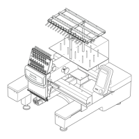
Procedure for removing and installing the rotary hook assembly.
Procedure for removing and installing the thread cutter.
Procedure for removing and installing the thread catcher.
Procedure for removing and installing the needle bar assembly.
Procedure for removing and installing the needle bar reciprocator.
Procedure for removing and installing the thread change motor.
Procedure for removing and installing the power supply board.
Procedure for removing and installing the power circuit board.
| Type | Embroidery and Sewing Machine |
|---|---|
| Automatic Needle Threader | Yes |
| Automatic Thread Cutter | Yes |
| Free Arm | Yes |
| Maximum sewing speed | 850 stitches per minute |
| Connectivity | USB |
| Speed Control | Yes |