17
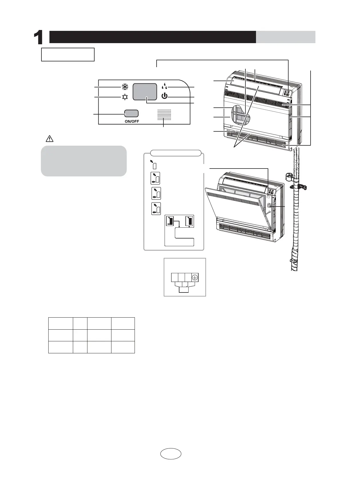
Air outlet selection switch
This setting blows air from
upper outlet only.
This setting automatically
decides a blow pattern
depending on mode and
conditions.
7KHXQLWLVVKLSSHGIURPWKH
factory with this setting.
7KLVVHWWLQJLVUHFRPPHQGHG
16
1
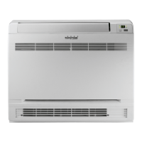
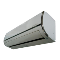
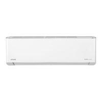
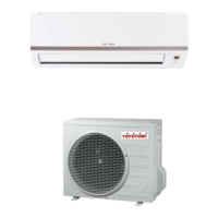
Part names and their functions
INDOOR UNIT
CAUTION
OPERATION INSTRUCTIONS
25ć
25ć
ķ If the supply cord is damaged, it must be replaced by the manufacturer or its service agent or a similarly qualified person in order to avoid a hazard.
Ĺ An all-pole disconnection switch having a contact separation of at least 3mm in all polesshould be connected in fixed wiring. For models with a power
plug, make sure the plugis within reach after installation.
ĸ The appliance shall be installed in accordance with national wiring regulations.
NOTE:
1. Titanium Apatite Photocatalytic
Air-Purifying Filter:
12. Run lamp
13. LED display
16.Air outlet selection switch
17.Room temperature sensor:
,WVHQVHVWKHDLUWHPSHUDWXUHDURXQGWKHXQLW
15.Signal receiver:
,WUHFHLYHVVLJQDOVIURPWKHUHPRWHFRQWUROOHU
:KHQWKHXQLWUHFHLYHVDVLJQDO\RXZLOOKHDU
a short beep.
6HWWLQJVFKDQJHGEHHS
14. Indoor Unit ON/OFF switch:
3XVKWKLVVZLWFKRQFHWRVWDUWRSHUDWLRQ
Push once again to stop it.
2. Air outlet
3. Display
4. Front panel
5. Louvers (vertical blades)
7KHORXYHUVDUHLQVLGHRIWKHDLURXWOHW
6. Air inlet
7. Air filter
8. Flap (horizontal blade)
9. Cool mode lamp
10. Heat mode lamp
11. Dry mode lamp
7KHVHILOWHUVDUHDWWDFKHGWRWKHLQVLGH
of the air filters.
7KHRSHUDWLRQPRGHUHIHUVWRWKHIROORZLQJWDEOH
7KLVVZLWFKLVXVHIXOZKHQWKHUHPRWHFRQWUROOHU
is missing.
Model Mode
Temperature
setting
Air flow rate
AUTO
AUTO
COOL
AUTO
COOLING
ONLY
HEAT
PUMP
Opening the Front Panel
Indoor unit
wiring terminal
N(1) 2 3
BU BK BN
<(//2:
GREEN
3
9
12
10
14
15
13
11
3
12
5
6
2
4
7
8
Before opening the front panel, be sure to
stop the operation and turn the breaker OFF.
Do not touch the metal parts on the inside
of the indoor unit, as it may result in injury.