Do you have a question about the TP-Link Omada Pro AP9650 and is the answer not in the manual?
This document outlines the installation and configuration of a Wireless Access Point, designed for robust network connectivity in various environments. The device supports multiple power supply options and can be managed either as a standalone unit or as part of a larger network through an Omada Controller.
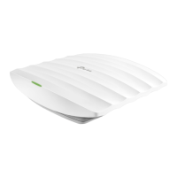
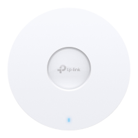
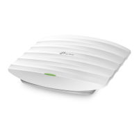
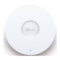
The Wireless Access Point serves as a central hub for wireless network connectivity, extending network coverage and providing reliable access for clients. It is capable of transmitting data and receiving power via Power over Ethernet (PoE) through its Ethernet port, or it can be powered by a standard electrical wall outlet using a power adapter. The device is designed to integrate seamlessly into existing network infrastructures, whether for small, isolated networks or larger, centrally managed systems. Its primary function is to provide Wi-Fi access, allowing various client devices to connect to the internet and other network resources wirelessly. The device's LED indicator provides visual feedback on its operational status, including normal operation, initialization, abnormal working conditions, power off, and various flashing patterns to indicate specific states such as initialization completion, upgrading, resetting, locating by the Omada controller, or being in an isolated state. This visual feedback is crucial for quick troubleshooting and status monitoring without needing to access the device's software interface.
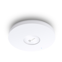
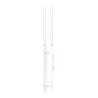
The Wireless Access Point offers flexible installation options, allowing it to be mounted on ceilings, walls, or in junction boxes. This versatility ensures that the device can be optimally positioned for maximum coverage and aesthetic integration into different environments. For ceiling mounting, the device requires a ceiling tile larger than the AP itself, and the process involves securing a mounting bracket to the tile using screws, washers, and wing nuts, then attaching the AP by rotating it into place. Wall mounting involves marking and drilling holes for plastic wall anchors and self-tapping screws, securing the mounting bracket, and then attaching the AP. Junction box mounting aligns the mounting bracket with existing junction box holes, routing cables, and securing the bracket before attaching the AP. These detailed installation steps ensure a secure and stable physical setup.
Powering the device can be achieved through two methods: via a PoE switch compliant with 802.3at, which simplifies cabling by delivering both data and power over a single Ethernet cable, or via a power adapter connected to a standard electrical wall outlet. This dual power option provides flexibility depending on the available infrastructure.
Software configuration offers two primary modes: Standalone Mode and Controller Mode. In Standalone Mode, the APs are configured and managed individually, which is convenient for small networks with only a few devices. This can be done via the Omada App or a web browser. Using the Omada App, users can download it to their mobile device, connect to the AP's default SSID, and then configure basic settings. For more advanced settings or for those preferring a desktop interface, a web browser can be used by connecting to the default SSID and navigating to http://tplinkeap.net. This allows for setting up a new username and password, modifying wireless parameters, and reconnecting wireless devices.
For larger networks, Controller Mode is recommended, allowing for batch configuration and central management of multiple APs through an Omada Controller. This controller can be either an Omada Software Controller, which runs on a PC with Windows OS or Linux OS, or an Omada Hardware Controller (OC200/OC300), a dedicated device that can be purchased separately. The Omada Controller needs to have network access to all Omada devices (router, switch, and APs) to find, adopt, and manage them. Configuration in Controller Mode can also be done via the Omada App or a web browser. The Omada App allows for local or remote management of the controller. For local management, users connect to the AP's default SSID, launch the app, and add the controller. For remote management, the controller needs to have Cloud Access enabled and bound to a TP-Link ID, allowing users to log in via the app and manage their controllers from anywhere. Similarly, via a web browser, users can access the Omada Controller's web page, complete a quick setup wizard, and then log in to configure the controller. Remote management through the web browser also leverages Omada Cloud Service, requiring Cloud Access to be enabled on the controller and bound to a TP-Link ID.
The device incorporates several features to facilitate maintenance and ensure long-term reliability. The LED indicator, as mentioned, is a key maintenance tool, providing immediate visual cues for various operational states. A quick glance at the LED can inform administrators about the device's health, whether it's working normally, undergoing an upgrade, or experiencing an issue that requires attention. For instance, a quickly flashing LED indicates that the AP is resetting or being located by the Omada controller, while a slowly flashing LED signifies an isolated state, prompting investigation into network connectivity.
The RESET button is a critical maintenance feature. With the device powered on, pressing and holding this button for approximately 5 seconds until the LED flashes quickly will restore the device to its factory default settings. This is invaluable for troubleshooting persistent configuration issues, recovering from incorrect settings, or preparing the device for redeployment. It provides a straightforward way to return the device to a known good state without requiring complex software procedures.
The design of the device, particularly its metal bracket, is noted for requiring heat dissipation during use. While this is a design consideration, it implies that the device is built to handle thermal loads, contributing to its stability and longevity. Users are advised to be careful not to touch the metal bracket during operation, indicating that the device is designed for continuous, high-performance use where heat management is essential.
The Omada Controller, whether software or hardware-based, offers centralized management capabilities that significantly streamline maintenance. Instead of individually accessing each AP for updates or configuration changes, administrators can manage all devices from a single interface. This includes pushing firmware updates, monitoring device status, and adjusting network settings across multiple APs simultaneously. The ability to remotely manage the controller via Omada Cloud Service further enhances maintenance flexibility, allowing administrators to perform tasks and monitor the network from any location with internet access. This centralized approach reduces the time and effort required for routine maintenance and allows for quicker response to network issues. The availability of a comprehensive User Guide for the controller and APs, accessible through the TP-Link support website, provides detailed instructions for advanced configurations and troubleshooting, empowering users to perform more in-depth maintenance tasks. Additionally, the TP-Link Community and technical support resources offer avenues for users to seek assistance, find answers, and communicate with engineers, ensuring ongoing support for device maintenance and operation.
| Model | AP9650 |
|---|---|
| Frequency Bands | 2.4 GHz, 5 GHz |
| 2.4 GHz Speed | 1148 Mbps |
| Antenna Gain (2.4 GHz) | 4 dBi |
| Antenna Gain (5 GHz) | 5 dBi |
| PoE Support | 802.3at PoE+ |
| Maximum Power Consumption | 25.5W |
| MU-MIMO | Yes |
| OFDMA | Yes |
| Beamforming | Yes |
| Centralized Management | Omada SDN Controller |
| Wireless Standard | 802.11ax |
| 5 GHz Speed | 4804 Mbps |
| Antenna Type | Internal |
| Ethernet Port | 1x 2.5 Gbps Ethernet Port |
| Dimensions | 243 x 243 x 64 mm |
| Mounting | Ceiling/Wall |
| Operating Temperature | 0°C to 40°C |
| Management | Omada App, Web, CLI |
| Weight | 1.1 kg (2.43 lb) |