Do you have a question about the TP-Link Omada EAP660 HD and is the answer not in the manual?
Explains the meaning of different LED light patterns for status indication.
Details the procedure to restore the device to factory default settings.
Describes the Ethernet and Power ports for network connection and power.
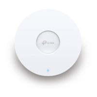
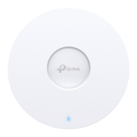
Step-by-step instructions for installing the EAP on a ceiling tile.
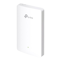
Step-by-step instructions for installing the EAP on a wall.
How to power the EAP using a PoE switch compliant with 802.3at.
How to power the EAP using the provided power adapter.
Guides for configuring EAPs individually via Omada App or Web Browser.
Guides for managing EAPs in batches using Omada Software or Hardware Controller.
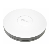
This document describes the TP-Link Omada Wireless Access Point, a device designed for robust wireless network management. It can be deployed in various environments, offering both standalone and centralized control options to suit different network scales and user preferences.
The Omada Wireless Access Point serves as a central component for establishing and extending wireless networks. It broadcasts Wi-Fi signals, allowing client devices to connect and access network resources. The device supports Power over Ethernet (PoE), enabling both power and data transmission through a single Ethernet cable, simplifying installation and reducing cable clutter. Alternatively, it can be powered via a standard power adapter. The access point is designed to integrate seamlessly with the Omada ecosystem, which includes software and hardware controllers for unified management of multiple EAPs.
The Omada Wireless Access Point offers flexible installation options, allowing for either ceiling or wall mounting. For ceiling mounting, the device can be secured to a ceiling tile using screws, washers, and wing nuts, with a dedicated hole for the Ethernet cable. Wall mounting involves securing a bracket to the wall using plastic anchors and self-tapping screws, ensuring the bracket's shoulders are on the outside for proper EAP attachment. Once the bracket is in place, the EAP is attached and rotated until it locks securely.
The device features an LED indicator that provides visual feedback on its operational status. A steady "On" light indicates normal operation or initialization, while "Off" signifies abnormal operation, power off, or the LED being turned off. Various flashing patterns communicate specific states:
Configuration and management can be performed in two primary modes:
This mode is suitable for smaller networks with a limited number of devices, where each EAP is configured and managed individually.
http://tplinkeap.net. The default login credentials (admin/admin) allow access to the management interface, where a new username and password can be set, wireless parameters modified, and the device reconnected to the new network. While basic functions are configurable here, advanced settings may require Controller Mode.This mode is designed for centralized management of multiple EAPs, providing a unified platform for configuration, monitoring, and troubleshooting. It leverages an Omada Controller, which can be either software-based or hardware-based.
https://omada.tplinkcloud.com), requiring Cloud Access to be enabled and bound to a TP-Link ID on the controller.The Omada Wireless Access Point includes a reset button for restoring factory default settings. To perform a reset, press and hold the button for approximately 5 seconds while the device is powered on, until the LED flashes quickly. Releasing the button will initiate the reset and subsequent reboot. This feature is useful for troubleshooting or reconfiguring the device from scratch.
For technical support, user guides, and other information, TP-Link provides resources on its official website and a community forum for users and engineers to interact. Safety information is also provided, advising users to keep the device away from water, fire, humidity, or hot environments, and to avoid disassembling, repairing, or modifying the device. It also emphasizes using only recommended chargers and ensuring the adapter is easily accessible.
| DC-in jack | Yes |
|---|---|
| Ports quantity | 1 |
| USB 2.0 ports quantity | 0 |
| MIMO type | Multi User MIMO |
| Frequency band | 2.4 - 5 GHz |
| Networking standards | IEEE 802.11a, IEEE 802.11ac, IEEE 802.11ax, IEEE 802.11b, IEEE 802.11g, IEEE 802.11n |
| Ethernet LAN data rates | 25000 Mbit/s |
| Maximum data transfer rate | 2402 Mbit/s |
| Maximum data transfer rate (2.4 GHz) | 1148 Mbit/s |
| Output current | 2 A |
| Output voltage | 12 V |
| Security algorithms | WPA-Enterprise, WPA-PSK, WPA2-Enterprise, WPA2-PSK, WPA3-Enterprise, WPA3-PSK |
| Service Set Identifier (SSID) features | Multiple SSIDs |
| Antenna type | Internal |
| Placement | Ceiling |
| Product color | White |
| Storage temperature (T-T) | -40 - 70 °C |
| Operating temperature (T-T) | 0 - 40 °C |
| Storage relative humidity (H-H) | 5 - 90 % |
| Operating relative humidity (H-H) | 10 - 90 % |
| Harmonized System (HS) code | 85176990 |
| Width | 243 mm |
|---|---|
| Height | 64 mm |