Do you have a question about the TP-Link Omada EAP620 HD V2 and is the answer not in the manual?
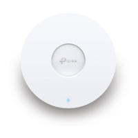
Details LED indicator states and the reset button function for the EAP.
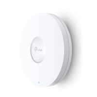
Describes the Ethernet and Power ports on the rear of the EAP.
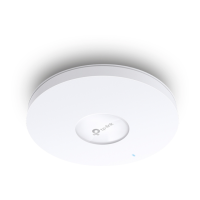
Step-by-step guide for mounting the EAP onto a ceiling tile.
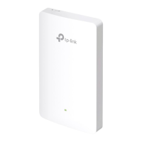
Step-by-step guide for mounting the EAP onto a wall.
How to connect the EAP to a PoE switch for power and data.
How to connect the EAP using the provided power adapter.
Configure EAPs individually via Omada App or web browser.
Centrally manage EAPs using Omada Software, Hardware, or Cloud Controllers.
This document outlines the setup and management of a Wireless Access Point, designed for both small-scale and large-scale network deployments. The device functions as a central point for wireless connectivity, allowing users to access a network wirelessly. It supports various deployment scenarios, including ceiling and wall mounting, and offers flexible power options.
The Wireless Access Point serves as a crucial component in extending wireless network coverage. It connects to a wired network, typically via an Ethernet port, and broadcasts a wireless signal, enabling client devices such as laptops, smartphones, and tablets to connect to the internet or local network resources. The device is designed to handle data transmission and, in some models, can receive power over Ethernet (PoE), simplifying installation by eliminating the need for a separate power adapter.
The core function revolves around providing reliable and high-speed wireless access. It supports different Ethernet speeds, ensuring compatibility with various network infrastructures. The device can operate in two primary modes: Standalone Mode for individual management, suitable for smaller networks, and Controller Mode for centralized management of multiple Access Points, ideal for larger, more complex environments.
In Standalone Mode, the Access Point can be configured directly via a mobile application or a web browser. This allows for quick setup of basic wireless parameters, such as SSID and password. For advanced configurations, users can access a more comprehensive interface through a web browser.
In Controller Mode, the Access Point integrates with a centralized management system, which can be an Omada Software Controller, an Omada Hardware Controller (like OC200/OC300), or an Omada Cloud-Based Controller. This mode enables administrators to manage multiple Access Points from a single interface, offering features like batch configuration, real-time monitoring, and advanced network settings. The controller can also facilitate remote management through a cloud portal or a dedicated mobile application, providing flexibility for network administrators to oversee their network from anywhere.
The Wireless Access Point offers several features designed to enhance usability and deployment flexibility:
The device incorporates features that facilitate maintenance and troubleshooting:
| Frequency Band | 2.4 GHz and 5 GHz |
|---|---|
| Wireless Standards | IEEE 802.11ax/ac/n/g/b/a |
| Antenna Type | Internal |
| Ethernet Ports | 1 x Gigabit Ethernet (RJ-45) Port |
| Power Supply | 802.3at PoE or 12V/1.5A DC |
| Mounting | Ceiling / Wall Mounting |
| Management | Omada App |
| Wireless Functions | MU-MIMO, Beamforming, Band Steering, Airtime Fairness |
| Wireless Security | WPA3, WPA2, WPA, 802.1X, MAC Filtering |