EasyManua.ls Logo

TP-Link Omada EAP115-Wall User Manual

TP-Link Omada EAP115-Wall
2 pages
To Next Page IconTo Next Page
Page #1 background imageLoading...
Page #1 background image
Hardware Overview
Quick Installation Guide
EAP115-Wall
300Mbps Wireless N Wall-Plate Access Point
Installation Steps
3
Front Panel
Rear Panel
LAN Port
RESET
LED
Pre-Installation Checklist
2
UPLINK+PoE Port
Connected to a PSE (Power Sourcing Equipment), such as a PoE switch, for
both data transmission and Power.
LED/Wi-Fi Button
When the EAP is working in Standalone Mode and enabled with Wi-Fi
Control, press the button to turn on/o both of the Wi-Fi and LED. In other
cases, press the button to turn on/o the LED only.
LAN Port
A wired device can be connected to the LAN port via an Ethernet cable
and access the network.
RESET
With the EAP powered on, press and hold the button for about 5 seconds
until the LED ashes. The EAP will restore to factory default settings.
LED Indicator
On: Working normally/Initializing.
O: Working abnormally/Power o/LED is turned o.
Flashing:
Initialization: The LED ashes twice after initialization is complete.
Upgrade: The LED ashes once per second while upgrading.
Reset: The LED ashes ve times in quick session during the reset. The
EAP will then reboot.
Before installation, be sure that you have the following items:
1. A pre-installed wall junction box
2. An RJ45 plug
3. A triangular screwdriver
EAP115-Wall can be mounted into either an 86mm wall junction box or a
standard EU wall junction box. The junction box should be pre-installed with a
running-in-wall Ethernet cable connected to a PoE switch.
LED/Wi-Fi Button
5. Press the faceplate of the EAP back into position.
Standard EU wall junction box86mm wall junction box
4. A Phillips screwdriver
5. A PoE switch
4. Insert the enclosed screws and tighten them with a triangular
screwdriver to secure the mounting bracket.
Note:
Do not over tighten the screws.
If the enclosed screws do not t the junction box, use the screws attached to the
junction box instead.
1
©2018 TP-Link 7106508202 REV2.1.0
1. Detach the faceplate of the junction box with a Phillips screwdriver
(demonstrated with an 86mm wall junction box).
2. Detach the faceplate of the EAP with a screwdriver.
3. Connect the Ethernet cable inside the junction box to an RJ45 plug.
Then connect the cable to the UPLINK+PoE port. Position the Ethernet
cable to ensure it is not strained.
Question and Answer IconNeed help?

Do you have a question about the TP-Link Omada EAP115-Wall and is the answer not in the manual?

TP-Link Omada EAP115-Wall Specifications

General IconGeneral
5 GHzNo
2.4 GHzYes
Frequency band2.4 - 2.4835 GHz
Cabling technology10/100Base-T(X)
Transmitting power15 dBmW
Networking standardsIEEE 802.11b, IEEE 802.11g, IEEE 802.11n
Virtual LAN featuresPort-based VLAN, VLAN mapping
Ethernet LAN data rates10, 100 Mbit/s
Transmitting power (CE)20 dBm
Maximum data transfer rate300 Mbit/s
Power consumption (typical)2.8 W
Power over Ethernet (PoE) type supportedPassive PoE
WAN connectionEthernet (RJ-45)
USB 2.0 ports quantity0
Ethernet LAN (RJ-45) ports2
PlacementWall
Product colorWhite
Antenna featuresIntegrated antenna
Antenna direction typeOmni-directional
Antenna gain level (max)1.8 dBi
Security algorithms802.1x RADIUS, HTTPS, WPA, WPA-PSK, WPA2, WPA2-PSK
Number of SSID supported8
Service Set Identifier (SSID) featuresMultiple SSIDs
Storage temperature (T-T)-40 - 70 °C
Operating temperature (T-T)0 - 40 °C
Storage relative humidity (H-H)5 - 90 %
Operating relative humidity (H-H)10 - 90 %
Compatible operating systemsWindows XP, Windows Vista, Windows 7, Windows 8, Windows 10
Package depth130 mm
Package width118 mm
Package height47 mm
Package weight190 g
Harmonized System (HS) code85176990
Sustainability certificatesCE, RoHS
Number of products included1 pc(s)
Weight and Dimensions IconWeight and Dimensions
Width86.8 mm
Height30.2 mm

Summary

Hardware Overview

Device Components and Ports

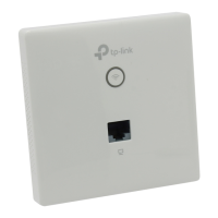
Details the EAP's front/rear panels, LED indicator, Wi-Fi button, LAN port, and reset function.

Installation Steps

Prepare and Attach Mounting Hardware

Detach junction box faceplates, connect Ethernet cable, and secure the mounting bracket.

Final EAP Attachment

Press the EAP's faceplate back into position to complete the installation.

Software Configuration Options

Standalone Mode Configuration

Guides users through configuring EAPs individually via the Omada App or a web browser.

Controller Mode Configuration

Explains batch management of EAPs using Omada Software Controller or OC200.

Omada App Management

Details how to manage EAPs locally or remotely using the TP-Link Omada mobile application.

Related product manuals